岸桥总体设计及起升机构设计研究(含CAD图,SolidWorks三维图)
1.无需注册登录,支付后按照提示操作即可获取该资料.
2.资料以网页介绍的为准,下载后不会有水印.资料仅供学习参考之用.
密 惠 保
岸桥总体设计及起升机构设计研究(含CAD图,SolidWorks三维图)(任务书,开题报告,论文说明书16000字,CAD图纸1张,SolidWorks三维图)
摘要
随着世界物流运输的飞速发展,同时也大大刺激了我国港口运输业的发展。其中集装箱运输具有载货量大、运输安全、装卸作业效率高等特点而被各个国家广泛采用。因此对岸边集装箱起重机的研究也显得十分必要。
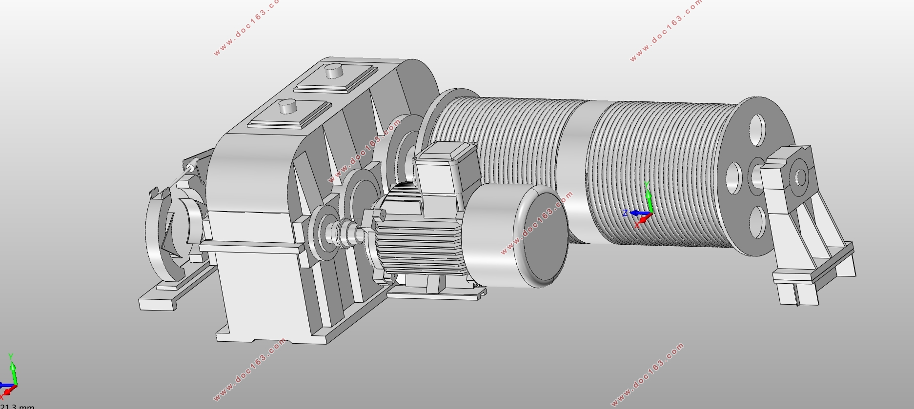
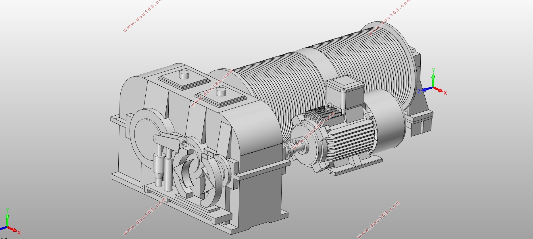
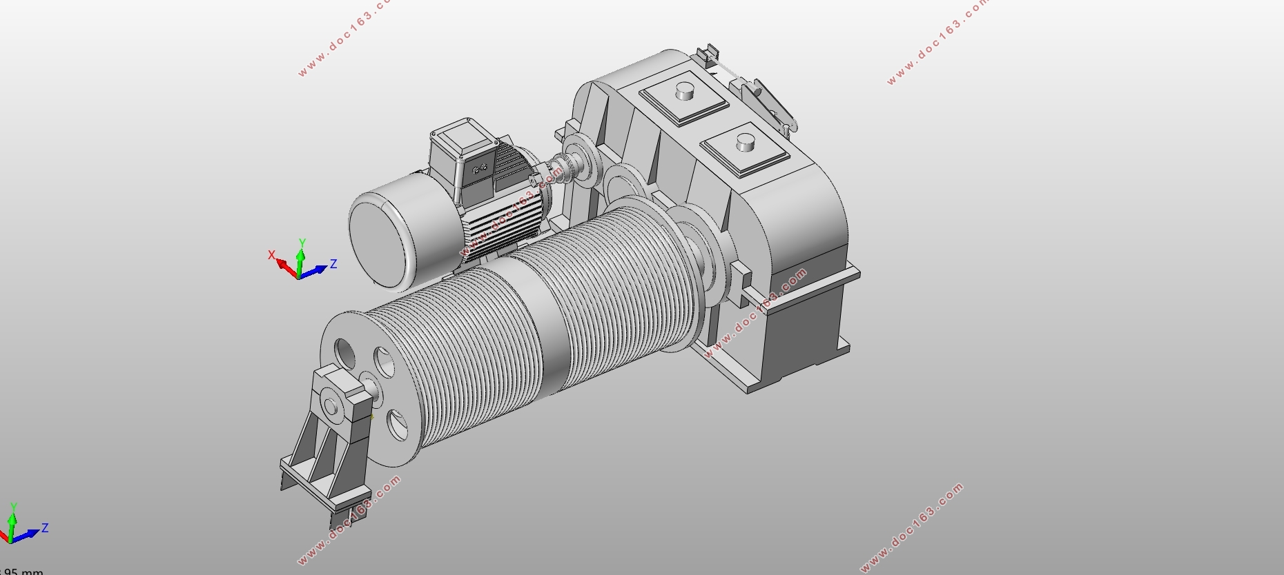
本文首先根据岸边集装箱起重机在国内外发展趋势的现状的分析,确定了本文的研究方向和技术路线。本文研究主要内容是以40.5T岸边集装箱起重机为对象,参照《岸边集装箱起重机》、《起重机设计手册》、《港口起重机》等资料,完成了对40.5T岸桥的总体设计和起升机构设计,运用Auto CAD、Solid Works等软件为研究工具,完成了起升机构的三维建模和动画模拟。
通过本次设计研究,熟悉了岸边集装箱起重机的设计过程,根据软件对起升机构的建模和动画模拟,也进一步加深了对岸桥起升机构的认识。为以后岸桥的创新设计打下了坚实的基础。
关键词:岸边集装箱起重机;起升机构;三维建模
Abstract
With the rapid development of the world's logistics and transportation, greatly stimulated the development of China's port transport industry. Which container transport with a large load, transport safety, loading and unloading operations and other characteristics of high efficiency widely used by various countries. So the study of the shore container cranes is also very necessary.
[来源:http://think58.com]
This paper first analyzes the current situation of the development trend of the container cranes at home and abroad, and determines the research direction and technical route of this paper. In this paper, the main contents of the study are 40.5T shore container cranes as the object, with reference to "shore container cranes", "crane design manual", "port crane" and other information, completed the 40.5T shore bridge overall design and hoisting institutions Design, using Auto CAD, Solid Works and other software as a research tool to complete the hoisting mechanism of the three-dimensional modeling and animation simulation.
Through this design study, familiar with the design process of the shore container crane, according to the software on the hoisting mechanism modeling and animation simulation, but also further deepen the understanding of the bridge crane mechanism. For the future of the bridge design innovative laid a solid foundation.
Key words :the container cranes;Hoisting mechanism;three-dimensional modeling
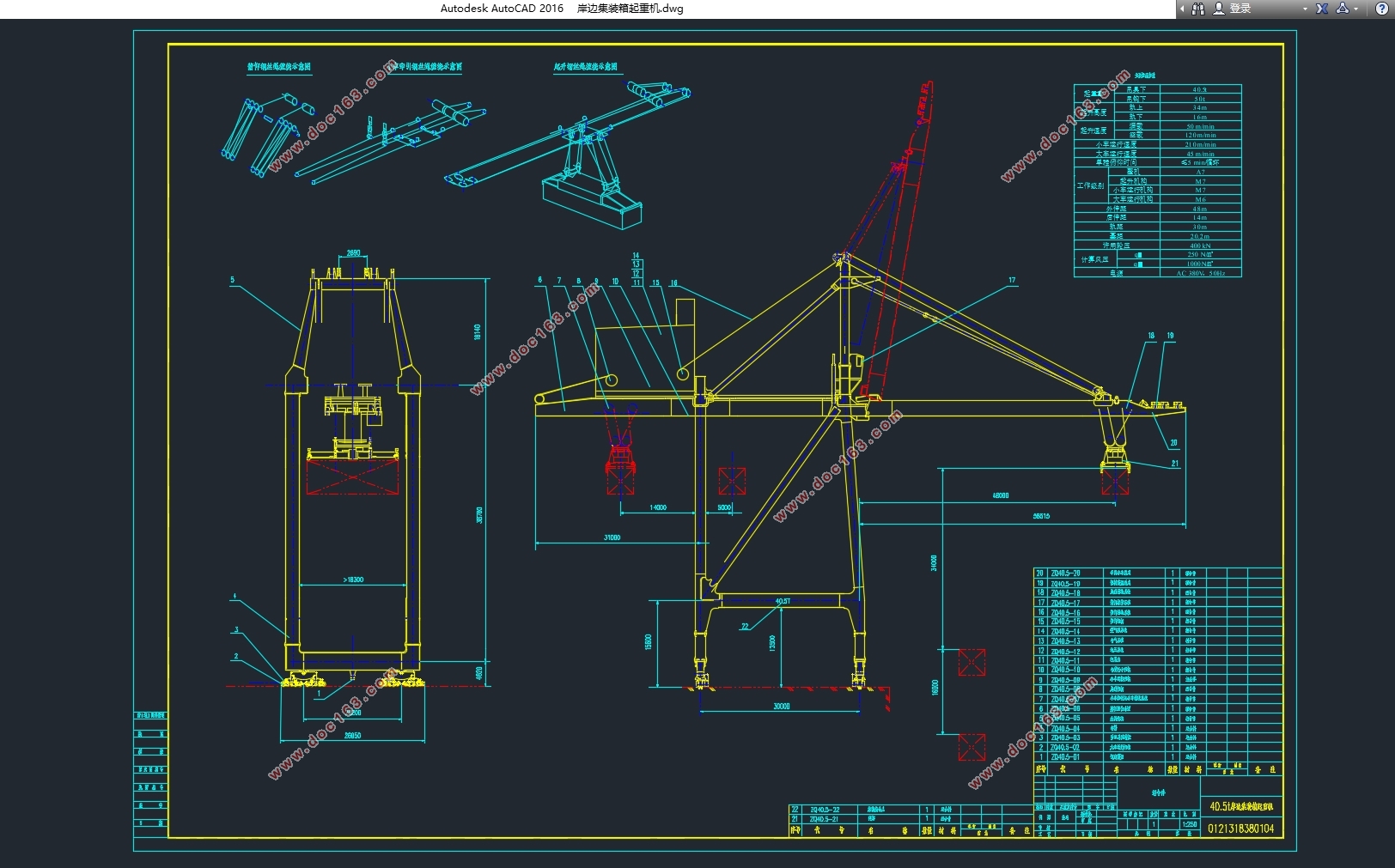
2.1.1设计参数
起重量(吊具下/吊钩下)40.5/50 t
起升高度(轨上/轨下)34/16 m
起升速度(满载/空载) 50/120 m/min
小车运行速度210 m/min
大车运行速度45 m/min
单程俯仰时间≤5 min/循环
工作级别整机A7
起升机构M7
小车运行机构M7
大车运行机构 M6
外伸距 48 m
后伸距14 m
轨距30 m
基距20.2 m
许用轮压400 kN
计算风压qII =250 N/㎡
qIII=1000 N/㎡
电源AC 380V,50Hz
[资料来源:www.THINK58.com]
目录
摘要 I [来源:http://think58.com]
Abstract II
1. 绪论 1
1.1 课题的研究目的及意义 1
1.2 国内外研究现状 1
1.3 本文工作 2
2. 总体设计及计算 3
2.1 确定工作机构的型式 3
2.1.1设计参数 3
2.1.2 起升机构 4
2.1.3俯仰机构 6
2.1.4运行小车机构 7
2.1.5大车行走机构 8
2.2 确定金属结构的型式 9
2.2.1岸桥的金属结构组成 9
2.2.2 门架 9
2.2.3 大梁结构 10
2.2.4 拉杆 10
2.3 载荷计算 10
2.3.1 自重及质心位置 11
2.3.2 运行机构产生的动载荷计算 14
2.3.3 风载荷计算 15
2.4 轮压计算 18
2.4.1工作状态下的轮压 18
2.4.2 非工作状态下的轮压 19
2.5 整机稳定性校核 21
2.5.1.无风静载工况下的稳定性 21
2.5.2 有风动载工况下的稳定性 21
2.5.3 暴风袭击下的非工作状态最大风载 22
2.6本章小结 23
3. 起升机构设计计算 24
3.1 起升机构的方案设计 24
3.1.1起升机构布置形式 24
3.1.2卷绕系统 24
3.1.3卷筒结构形式 24
3.2 起升机构设计计算 25
3.2.1 总体设计参数 25
3.2.2 钢丝绳选型计算 25
3.2.3滑轮选型计算 26
3.2.4卷筒设计计算 26
3.2.5起升电动机的选型 27
3.2.6 减速器选型计算 28
3.2.7制动器选型计算 29
3.2.8联轴器选型 30
3.2.9起升机构启动时间和启动加速度验算 30 [资料来源:http://www.THINK58.com]
3.2.10起升机构制动时间和制动加速度验算 31
3.3 吊具倾转运动的实现 32
3.3.1结构形式 32
3.3.2动作原理 33
3.4本章小结 33
4. 起升机构的三维建模 34
4.1 Solid Works软件简介 34
4.2 零部件模型的建立 34
4.2.1草图绘制 35
4.2.2 实体绘制 35
4.2.3 起升机构各零部件模型的绘制 35
4.3 起升机构的装配 37
4.3.1设计思路 37
4.3.2装配过程 37
4.4 本章小结 39
5. 总结与展望 40
5.1总结与展望 40
5.2 经济性分析 40
5.3 环保性分析 41
参考文献 42
致谢 43 [来源:http://think58.com]
