液压上料送料机械手设计(含CAD零件图装配图)

1.无需注册登录,支付后按照提示操作即可获取该资料.
2.资料以网页介绍的为准,下载后不会有水印.资料仅供学习参考之用.
密 惠 保
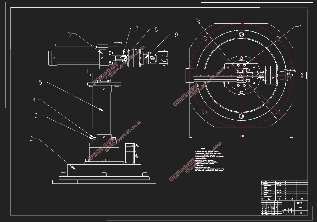
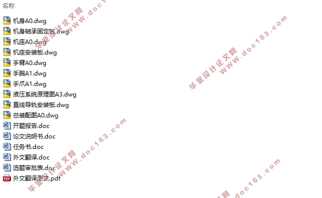
液压上料送料机械手设计(含CAD零件图装配图)(选题审核表,任务书,开题报告,外文翻译,论文说明书14000字,CAD图10张)
Design of Feed Manipulator
摘 要
随着全球经济一体化的发展,当今的机械制造设备越来越往机械自动化方向发展。机械手作为代替人手工上料在现代化机械制造中被普遍应用。液压上料机械手就是机械手中一种常见的应用。这些液压上料机械手被应用于各个机械设备领域,并且对于现在的高新技术来说是不可分割的。现在,工业生产实现了自动化。许多困难的工作环境或者一些人不方便做的工作都由送料机械手来完成。
送料机械手和液压系统都是紧密相关的,本次毕业设计是研究一款液压上料机械手。利用我们大学四年所学的机械专业知识查阅各种相关资料和文献,了解和熟悉其工作原理,首先根据设计任务书要求及参数对液压上料机械手提出总体的方案设计,然后通过各种三维二维机械制图软件对液压上料机械手进行结构设计,并绘制相关图纸,最后对液压上料机械手的零部件进行受力分析及强度校核。
关键字: 机械手;AutoCAD;Solidworks;液压系统
Abstract
The development of science and technology is getting better and better, so artificial intelligence has also made rapid progress. The most typical is the hydraulic loading manipulator, a variety of hydraulic loading manipulators. These hydraulic loading manipulators are used in various fields and are inseparable for the current high-tech. Now, industrial production is automated. Many difficult working environments or work inconvenient for some people are completed by hydraulic loading robots. The civilization of our human society is progressing. These progresses are closely related to the hydraulic loading manipulator. At present, the hottest scientific issue is the design of the hydraulic loading manipulator. In our country, although the research start time of the hydraulic loading manipulator is slower than other European and American countries, the level of hydraulic feeding manipulator in China has reached a very high level.
This graduation project is a hydraulic loading manipulator, its structural design and gait research. According to the needs, and in contact with the nature of the motor drive, the hydraulic loading manipulator operator of the hydraulic loading manipulator of some transmission devices is adopted. The practicality of the hydraulic loading manipulator produced is relatively high. This design is to use the knowledge we usually learn and some auxiliary links, the purpose is to initially understand the design process of electromechanical transmission. Drawing is the most critical in design. Drawings can show the content clearly, and it is also a certain test of our design level.
Key Words: Manipulator;AutoCAD;Solidworks;Hydraulic system
2.1.3 手爪参数和驱动力的计算
根据设计任务书得知, 在本次设计的设计当中设置机械手手的手抓夹紧力为500N,即克服工件自重的静载荷和工件运动状态变化的惯性力的载荷。根据图形中手爪的结构推测手爪当中的a结构尺寸为30mm,b结构的尺寸为65mm,a角的度数为40°。
通过下列公式2.2能够把驱动力F的数值计算出来: [资料来源:www.THINK58.com]
F=2b(cosα)2FN/a
=2×65×(cos40°)2×500/30
≈1271.5N
由此,我们能够得出实际的驱动力F应按以下公式进行相应的计算,也就是能够得出:
F实=FK1K2/η (2-3)
式中:η是手部的机械效率的表示形式,它的取值区间在0.85~0.95之间;
K1是安全系数的表示形式,它的取值区间在1.2~2之间;
K2是工作情况系数的表示形式,出于对惯性力的有效影响,K2的数值能够按照下列的式子来进行相应的计算,K2=1+a/g,在公式当中表示的是被抓取工件运动时的最大加速度,g在其中表示的是重力加速度。
结合说明书考虑实际情况,我们能够得出机械手爪以0.5m/s的速度在移动,并且是以1m/s2的加速度移动,最终能够通过公式2.3来把实际情况当中的驱动力计算出来:
F实=FK1K2/η
=1271.5×2×(1+1/9.8)/0.85
[版权所有:http://think58.com]
≈3291N
通过对以往设计的观察与研究,能够得出V型夹具张开的角度与活塞杆的移动距离有着莫大的联系,当单爪张开角度的取值区间在40°-50°之间的之后,那么能够得出活塞杆的行程L的数值选取的是:
L=a/tanα
=30/tan50°
≈25.17mm
我们能够得出在圆整之后它的数值选取的是26mm,能够与本次设计所需的条件相吻合。
[来源:http://www.think58.com]


目 录
第1章 绪 论 1
1.1 机器人 1
1.2 机械手 4
1.3 课题研究意义 5
第2章 机械手抓取机构设计 6
2.1手指手爪的设计计算 6
2.1.1 手指手爪设计要求 6
2.1.2 手指手爪的力学分析 7
2.1.3 手爪参数和驱动力的计算 8
2.1.4 手爪定位误差分析 9
2.1.5 手爪驱动油缸设计 11 [资料来源:www.THINK58.com]
2.2腕部设计计算 13
2.2.1 腕部设计要求 13
2.2.2 腕部驱动力矩设计计算 13
2.2.3 腕部摆动液压马达设计 16
2.3 臂伸缩机构设计计算 17
2.3.1 臂伸缩机构设计要求 17
2.3.2 臂伸缩机构油缸的设计计算 18
2.3.3 直线导轨滑块导向机构设计 20
第3章 机身机座的结构设计 21
3.1 机身升降机构设计 22
3.1.1 升降油缸设计 22
3.1.2 升降导向结构设计 23
3.2 机身回转机构设计 23
3.2.1 驱动电机设计计算 24
3.2.2 机身回转支撑结构设计计算 25
第4章 液压系统原理设计 27
4.1供油装置系统原理设计 28
4.2手爪油缸液压原理 29
4.3 腕部摆动液压马达原理 30
4.4 臂部伸缩油缸液压原理 31 [资料来源:http://think58.com]
4.5 机身升降油缸液压原理 32
4.6机械手总体液压系统原理图 33
第5章 机械手的定位和控制 35
5.1机械手的定位 35
5.2 机械手的控制 36
总 结 37
参考资料 39
致 谢 41 [资料来源:http://THINK58.com]
