
可调节式链传动式盘类形状上下料仓设计(含CAD零件装配图)
1.无需注册登录,支付后按照提示操作即可获取该资料.
2.资料以网页介绍的为准,下载后不会有水印.资料仅供学习参考之用.
密 惠 保
可调节式链传动式盘类形状上下料仓设计(含CAD零件装配图)(任务书,设计说明书9800字,CAD图纸9张)
摘 要
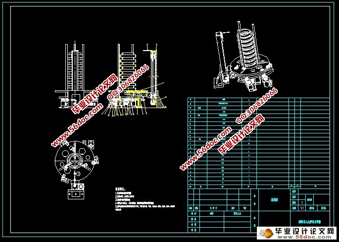
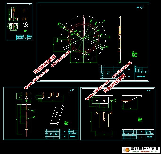
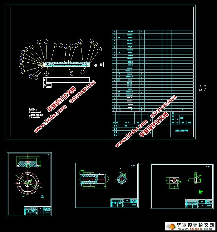
针对现代自动化流水线设计的一种圆盘类零件自动上料机构,实现了坯料的自动上料、夹紧以及坯料的放取。整个机构装置主要由料盘,坯料、夹具,动力输送系统以及控制系统组成。零件的定位、夹紧由料盘三根导杆通过下面的齿轮传送动力实现,导杆具有初步定位与夹紧的功能,实现坯料的定位和夹紧。坯料的抓取、回放是由夹具机械手通过上下伸缩、旋转等运动实现,动力为空气,气缸为执行部件。整个设计,为了实现工件的自动上料,三个导向杆同时向内或是向外运动,保持三者的同步性,通过使用链条齿轮传动,能够高效的保证三者同步性。考虑到所坯料的实际尺寸、质量等因素,整个机构采用了气动、链轮传送以及电气控制来实现了坯料的抓取,彻底实现自动化过程。
针对今生第一次,也许是今生的最后一次设计任务,我认真的阅读了老师给的任务书,充分了解了此次的设计任务、要求,与相关的技术参数。我花费了大量的时间在网海与书海里查找了大量的资料文献。在书的海洋里,我慢慢的找到了设计的灵感,诸多的各种机械结构在脑海里闪现。确定了我的上料仓系统的物料为圆柱类零件,要求输送这些物料到指定的位置。通过逻辑分块方法逐步分部设计各个工位板块。在solidworks里逐步的模拟设计每一个工位,然后优化结构,最后确定各部分机械结构。整个设计中,动力系统采伺服电机做为动力源;料仓是由圆盘与导杆组成,机构简单,成本低廉。伺服丝杠电机推动支撑座与料仓圆盘到定位面,实现了零件的定位,之后机械手在该平面进行准确的抓取;整个系统采用PLC控制系统,控制伺服电机的运转,从而控制提升圆盘料仓到准确位置。
[资料来源:http://think58.com]
整篇论文中包含设计方案的概述,主体机械机构和部分机械机构动力的计算,最终选定合适的伺服电机。本设计的目的在于:可调节式链传动式盘类形状上下料仓设计功能的实现,并且实现了自动化的生产目的,提高了生产效率,增加了企业的产能,降低工人的劳动强度。整个料仓的设计响应了国家提出的绿色环保的生产理念。并真实的实现这一目标!
关键词: 自动上料;夹具;料盘
Abstract
According to the automatic feeding mechanism of the disc type parts designed for the modern automatic assembly line, the automatic feeding, clamping and the placing of the blank are realized. The whole mechanism device is mainly composed of a material plate, a blank, a clamp, a power delivery system and a control system. The positioning and clamping of the parts are realized by the transmission power of the three guide rods of the material plate through the gear transmission, the guide rod has the function of preliminary positioning and clamping, and realizes the positioning and clamping of the blank. The grabbing and playback of the blank is realized by the movement of the manipulator of the fixture through the upper and the lower telescopic, the rotation and the like, the power is the air, the cylinder is the executive component. The whole design, in order to realize the automatic feeding of the workpiece, the three guide rods at the same time inward or outward movement, to maintain the synchronization of the three, through the use of chain gear drive, can effectively ensure the synchronization of the three. Taking into account the actual size of the blank, quality and other factors, the whole body using the pneumatic, sprocket transmission and electrical control to achieve the blank grab, complete automation process. [来源:http://think58.com]
For the first time in this life, perhaps the last design task of this life, I carefully read the teacher to the task book, fully understand the design tasks, requirements, and related technical parameters. I spent a lot of time in the sea and sea search book lots of documents. In the book of the ocean, I slowly found the design of inspiration, many of the mechanical structure of the flash in my mind. Identify the bin my system material for the cylinder parts, requires delivery of these materials to the designated position. By using the logical block method, the design of each station plate. Gradually in the SolidWorks simulation design every station, and then optimize the structure, and finally determine the various parts of the mechanical structure. The whole design, power system production servo motor as a power source; storage bin is composed of a disc and a guide rod mechanism is simple and low cost. Screw servo motor drive supporting seat and hopper disk to locate the face, to achieve the positioning parts, mechanical hand in the plane of accurate grasp; the whole system adopts PLC control system, operation control of a servo motor to control upgrade disk bin to the accurate position.
[来源:http://think58.com]
The whole paper includes an overview of the design of the project, the main body of mechanical mechanism and the calculation of the power of mechanical structure, the final selection of the appropriate servo motor. The design objective is: implementation of silo design function on regulating chain type transmission type disc shape, and the realization of the automation of production, improve production efficiency, increase the production capacity of enterprises, reduce the labor intensity of the workers. The whole design of the hopper in response to the state of green production concept. And to achieve this goal
Keywords: Automatic feeding、fixture、Material tray
可调节式链传动式盘类形状上下料仓设计的关键参数
1.回转型可调节式盘类形状零件上下料仓设计的回转移动最大运行速度为:0.3m/s。
2.每个工件的质量假定为: 2kg<工件<4kg
3.单个料盘的所容纳零件的总重量为:<50Kg
4.横向移动的料盘的数量为16个,其中在端部的一个为上料工位,另一个为下料工位。
[资料来源:http://think58.com]
5.零件的形状:
零件的直径范围:80-300mm
高度范围为:30-70mm
[资料来源:www.THINK58.com]
目 录
引言 1
第一章概述 2
1.1 可调节式链传动式盘类形状上下料仓设计概述 2
1.2 可调节式链传动式盘类形状上下料仓设计组成及其作用 2 [资料来源:http://THINK58.com]
1.2.1可调节式链传动式盘类形状上下料仓设计的组成 2
1.2.2可调节式链传动式盘类形状上下料仓设计的作用 3
第二章总体方案设计 4
2.1 可调节式链传动式盘类形状上下料仓设计的关键参数 4
2.2 可调节式链传动式盘类形状上下料仓设计的传动方案设计 4
2.2.1 传动方式的设计 4
2.2.2 料盘整体的设计方案 5
2.2.3 动力提升的设计方案 6
2.3 可调节式链传动式盘类形状上下料仓设计伺服电机的选择 8
2.3.1料仓设计伺服电机功率的选择 8
2.3.2料仓设计滚珠丝杠行程的选择 12
第三章可调节式链传动式盘类形状上料仓的主体结构设计 13
3.1可调节式链传动式盘类形状上料仓设计的工装结构设计 13
[来源:http://think58.com]
第四章 基于料仓设计的建模及装配 15
4.1solidworks软件建模与装配概述 15
4.1.1结构设计的基本概念 15
4.1.2 Solidworks软件在结构设计中的作用 15
4.2 运用Solidworks软件进行零件设计 16
4.3运用Solidworks软件进行零件的装配 19
图4-8 整个装配体总装图 20
结论 21
参考文献 22
致谢 23
[来源:http://www.think58.com]