仿形车床上(下)料机械手的设计(三维Proe)☆

1.无需注册登录,支付后按照提示操作即可获取该资料.
2.资料以网页介绍的为准,下载后不会有水印.资料仅供学习参考之用.
密 惠 保
摘 要
花键轴自动线是由三台仿形车床组成。料道的方向与机床主轴平行。上料及下料分别有两个机械手来完成,其机构基本相同。对年生产纲领为10万件的花键轴,其加工工艺要求在一台机床上一次完成花键轴的外圆加工及花键加工。当自动机床完成对工件的切削加工以后,若能设计机械手自动完成工件上下料运动,同时完成工件的翻转运动,则可以形成自动线而大大提高工作效率。
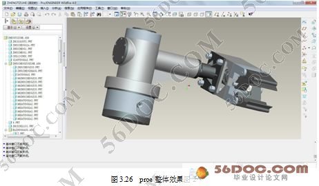
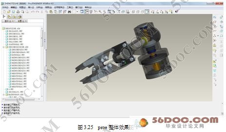
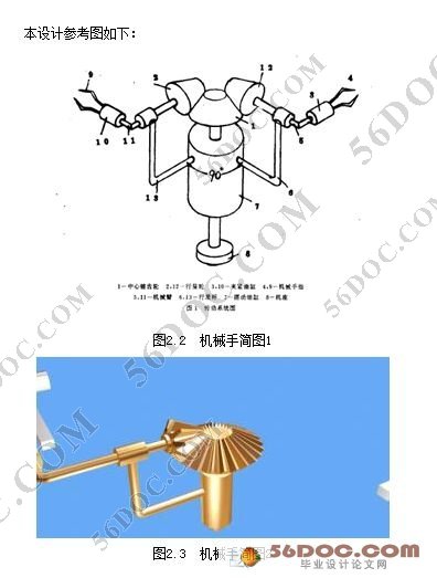
本设计着重讨论了花键轴自动线上,下料机械手的运动特点、驱动方式以及控制方式,为机械手的具体结构设计提供了理论依据。现以下料机械手为例,下料机械手是把已加工好的工件从机床上取下,转送到下一个工位的料道上。机械手系由旋转油缸、夹紧油缸、锥齿轮的行星机构及手爪组成。机械手共有两个动作:机械手转臂的正、反回转运动;手爪的夹紧与放松运动。
机械手基本参数:手臂回转角度90o。机械手的回转缸的转轴通过花键带动手臂回转。由于中心锥齿轮固定不动,小臂就带动行星锥齿轮做复合运动(即绕中心锥齿轮线公转,又绕自身轴自转)。两锥齿轮的齿数比为2:1,所以当大手臂转过90o
时,行星锥齿轮自转转过180o(即手腕运动)。加持式手部及夹紧油缸装在手臂上,由手臂带动加持式手部走空间曲线轨迹,将工件装到机床顶尖处(上料),或从机床顶尖处取下工件送到料道上去(下料)。
生产中,一台仿形车床使用两个完全相同的机械手,分别装、卸工件,动作灵活可靠。
关键词:机械手 设计 机械回路 电控回路
Abstract
By three spline automatic line is a parody of fractal lathe. The direction of the feeding word spindle parallel. On material anticipates two manipulator respectively, the agency to complete basic and same. Annual production program for 10 million pieces of spline shaft, its processing technology requirements in a machine last completed a circular spline processing and spline processing. When completed the automatic machine of workpiece machining later, if can design manipulator automatic completion of workpiece up-down material movement, finish at the same time, the flip of workpiece can form automatic line movement and greatly improving working efficiency.
This design emphasizes to discuss the material on spline automatic line, the motion characteristics, driven manipulators and control mode for the way of the manipulator, concrete structure design provides theory basis. Now the following materials for example, blanking robot manipulators is already processed to remove from machine workpiece, transferred to a location on the material under. Manipulator by rotating cylinder, of clamping cylinder, bevel gear planetary institutions and PAWS composition. Manipulator has two action: manipulator turn arm the positive and negative rotation movement; The PAWS clamping and relaxation exercises. [版权所有:http://think58.com]
Manipulator basic parameters: the arm turning Angle 90o. Rotary cylinder shaft of the manipulator arm backwards. Driven by spline Because central bevel gear stationary, and forearm will drive the planet bevel gear do compound movement around the center line (i.e. revolution, and bevel gear around their axis). The two bevel gear ratios for 2:1, so when big turn 90o arm
, the planet rotate 180o (i.e. bevel gears turn wrist movements). The blessing type hand and clamping cylinder packed in the arm, driven by arm hand go add hold type space curve track, the workpiece was loaded to machine's top place (feeding), or take the top place from machine to material way up (workpiece material).
Production, a copy form lathe to use two identical manipulator, are installed, unloading workpieces, flexible motion and reliable.
Keywords: manipulator control circuit design mechanical loop
本篇设计的机械手综合和运用了机械零件、理论力学、材料力学、机械原理、金属工艺学、热处理、技术测量、机械制图等知识,它主要是应用在那些单调、频繁的操作中用以代替人的劳动进行工作,它的主要优点是: [资料来源:http://think58.com]
1. 工作时间持久,不会出现人的疲劳,可以重复不断的劳动,维持流水线的正常工作。
2. 对环境适应性强,可以在多粉尘、易燃、易爆、放射性强等恶劣环境中工作。
3. 运动精确、灵活、特别是在计算机的控制下,可以达到非常高的精度要求。
4. 通用性好,除了特定用途外,适当改变手部,便可以完成喷涂、焊接等。
5. 工作效率高,提高劳动生产率的同时也提高了成本。
本机械手可以根据需要加上行走机构,以便实现远距离操作。
本次设计的机械手是以PLC控制个液压元件来实现机械手各关节的运动。至于机械手在空间的运动和定位则由外部的电脑操作系统完成,它主要先进行机器手的运动学分析,动力学分析,轨迹规划和编程。从而由上述系统完成整个机械手在空间的行走,定位和重复定位等操作。
电控线路图如图所示,具体设计从略。
2.2 规格参数
工业机械手的规格参数是说明机械手规格和性能的具体指标,一般包括以下几个方面:
1.抓重(又称臂力):额定抓取重量或称额定负荷,单位为公斤;
2.自由度数目和坐标形式:整机,手臂和手腕等运动共有几个自由度,并说明坐标形式;
3.定位方式:固定机械挡块,可调机械挡块,行程开关,电位器及其他各种位置设定和检测装置; [资料来源:http://THINK58.com]
4.驱动方式:气动,液动,电动和机械式四种形式;
5.手臂运动参数;
6.手腕运动参数;
7.手指夹持范围和握力;
8.定位精度:位置设定精度和重复定位精度;
9.轮廓尺寸:长×宽×高(毫米);
10.重量:整机重量。
2.3 设计路线与方案
2.3.1 设计步骤
1.查阅相关资料;
2.确定研究技术路线与方案构思;
3.结构和运动学分析;
4.根据所给技术参数进行计算;
5.按所给规格,范围,性能进行分析,强度和运动学校核;
6.绘制工作装配图草图;
7.绘制总图及零件图等;
8.总结问题进行分析和解决。
[资料来源:http://THINK58.com]
[版权所有:http://think58.com]
目 录 15000字
摘 要 I
Abstract II
目 录 III
第1章 绪 论 1
1.1 工业机械手概况 1
1.2 工业机械手的分类 3
1.3 工业机械手在工业生产中的应用 4 [来源:http://www.think58.com]
1. 4机械手的发展趋势 5
1.5 本章小结 6
第2章 工业机械手的设计方案 7
2.1 工业机械手的组成 7
2.2 规格参数 8
2.3 设计路线与方案 8
2.3.1 设计步骤 8
2.3.2 研究方法和措施 9
第3章 机械手各部分的计算与分析 10
3.1 手部计算与分析 10
3.1.1 滑槽杠杆式手部设计的基本要求 10
3.1.2 手部的计算和分析 10
3.1.4 油缸端盖的连接方式及强度计算 16
3.2 腕部(小臂)计算与分析 18
3.2.1 腕部设计的基本要求 18
3.2.2 腕部回转力矩的计算 18
3.2.4 选键并校核强度 21
3.3 臂部(大臂)计算与分析 21
3.3.1 臂部设计的基本要求 21
3.3.2 手臂的设计计算 25
3.4 机身 33 [版权所有:http://think58.com]
3.5本章小结 33
第4章 液压系统 34
4.1 液压回路系统的设计 34
4.2 本章小结 35
第5章 液压缸的保养与维修 36
5.1 液压元件的安装 36
5.2 液压系统的一般使用与维护 36
5.3 一般技术安全事项 37
第6章 机械手控制系统 38
6.1 电控状态下机械手运动分析 39
结 论 40
参考文献 41
致 谢 42 [版权所有:http://think58.com]
