PN25\DN500双缸气动闸阀的设计(含CAD零件图装配图)

1.无需注册登录,支付后按照提示操作即可获取该资料.
2.资料以网页介绍的为准,下载后不会有水印.资料仅供学习参考之用.
密 惠 保
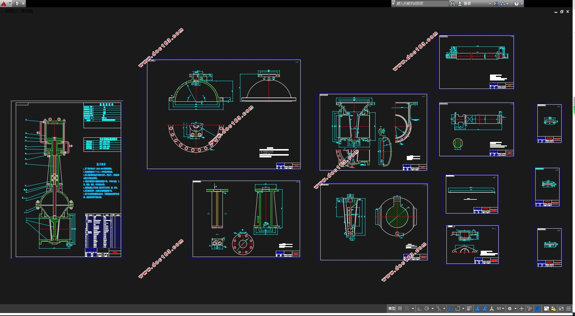
PN25\DN500双缸气动闸阀的设计(含CAD零件图装配图)(任务书,开题报告,论文说明书14000字,CAD图12张)
摘 要
阀门是管路流体输送系统中控制部件,它是用来改变通路断面和介质流动方向,具有导流、截止、调节、节流、止回、分流或卸压等功能。用于流体控制的阀门,从最简单的截止闸阀到复杂的自控系统中所用的各种阀门,其品种和规格繁多,阀门的公称通径从极微小的仪表阀大至通径达到 10m 的工业管路用阀。阀门可用于控制水、蒸汽、油品、气体、泥浆、各种腐蚀性介质、液态金属和放射性流体等各种类型流体的流动,阀门的工作压力可从 0. 013MPa 到 1000MPa 的超高压,工作温度从-269℃的超低温到1430℃的高温。阀门的控制可采用多种传动方式,如手动、电动、液动、气动、涡轮、电磁动、电磁-液动、电-液动等;可以在压力、温度或其他形式传感信号的作用下,按预定的要求动作,或者不依赖传感信号而进行简单的开启或关闭,阀门依靠驱动或自动机构使启闭件做升降、滑移、旋摆或回转运动,从而改变其流道面积的大小以实现其控制功能。
闸阀是指关闭件(闸板)沿通路中心线的垂直方向移动的阀门。闸阀在管路中只能作全开或全关切断用,不能作调节和节流。闸阀是使用范围很广的一种阀门,一般口径DN≥50mm 的切断装置都选用它,有时口径很小的切断装置也选用闸阀。 [资料来源:THINK58.com]
本设计是以楔式弹性单闸板闸阀为设计对象,主要介绍了闸阀的结构特点和手动气动转换装置的特点,以及其工作原理。阀门设计包括很多内容,包括通用部件的设计和专用部件的设计,又包括强度、尺寸等众多计算过程。其中,设计阀门的关键在于阀门密封设计,其中阀杆的强度计算,以及稳定性计算也是重点。
阀门设计整个过程包括这样几个步骤。按设计参数确定结构,进行方案论证,工作原理受力分析,强度计算,稳定性校核,材料选择,测绘总装备图和手动机构装配图和气缸及阀门的全部零件图(用 Auto CAD 绘制)。闸板密封面的受力分析,闸杆稳定性校核及阀门强度计算是重难点。其中包括这样几个重点步骤。首先对工作环境进行确定,选择合适的方案,对设计的零件进行受力分析;然后根据国家标准和推荐尺寸来确定实际尺寸;最后对强度进行校核,绘制阀门工程图。
关键词:手动—气动转换 密封面 楔式闸阀 弹性闸
Abstract
Valves is the control unit of the fluid piping system. It is used to change the channel sections and put to medium flow, with diversion, off, adjust the throttle, only the back, split or pressure relief function. For fluid control valves, cut-off valve from the simplest to the Commission for Discipline Inspection of complex automation systems used in a variety of valves, and its many varieties and specifications, the valve nominal diameter gauge valve from tiny to large diameter to 10m, industrial piping valves. The valve can be used to control the water, steam, oil, gas, slurry, a variety of corrosive media, liquid metals and radioactive fluid and other types of fluid flow. Working pressure of the valve from 0. 013MPa to 1000MPa. Working temperature from -269℃ to 1430℃ ultra-low temperatures. Valve control can be a variety of transmission methods, such as manual, electric, hydraulic, pneumatic, turbine, electromagnetic moving, electromagnetic - hydraulic, electro - hydraulic, etc. In pressure, temperature or other forms of sensor signals under the effect of a predetermined action required, or is not a simple sensing signal and open or close the valve mechanism relies on the drive or automatic opening and closing member to make movements, slip , swing or rotary motion. Thus changing the size of the flow passage area to achieve its control function.
[资料来源:http://think58.com]
Valve is closed parts (ram) along the channel centerline vertical movement of the valve. Valve in the pipeline can only be fully open or fully closed off with, can not be adjusted and the throttle. Valve is to use a wide range of a valve, generally diameter DN ≥ 50mm cutting devices are used which, sometimes a small diameter cutting device also use valve.
The design is flexible wedge gate valve for the design of single objects. Mainly introduced the structure characteristics of Gate. Manpower-Pneumatic the conversion device characteristic and operating principle. The valve is designed including many content. Include component design being applied or used universally and special use part design. And a lot of calculation process such as including the intensity, the dimension. Among them, design that the valve key depends on valve hermetic sealing
designs that. Among them the valve stem intensity secretly schemes against. The stability is calculated being also difficult point.
The valve is designed including such step. Design parameters determined by the structure, conduct demonstration program, working principle stress analysis, strength calculation, stability check, material selection, mapping diagrams and the General Armament manual mechanism and cylinder and valve assembly drawings for all the parts diagram (with Auto CAD drawing). Including such several priority step. First be in progress to the work environment thinking.
Choose the right scheme be in progress to the part designing that by force analysis. Then come the standard and recommendation according to the country to ascertain the actual dimension. Last the intensity is proofread, draw valve engineering drawing.
Keywords: the hand pneumatic change seal dyadic valve of wedge elasticity brake board
[来源:http://think58.com]


目 录
摘 要 I
Abstract II
第一章 绪 论 1
1.1 选题意义 1
1.2 国内外阀门的发展 1
1.2.1 国外阀门的发展 2
1.2.2 国内阀门的发展 2
第二章 气动—手动楔式闸阀的工作原理及其结构特点 3
2.1 工作原理 3
2.2 结构设计特点 5
第三章 阀门的设计与计算 7
3.1 阀体的设计与计算 7
3.1.1 阀体的功能 7
3.1.2 阀体的选材 7
3.1.3 阀体的结构形式和制造方法 8
3.1.4 确定阀体的结构长度和连接尺寸 8
3.1.5 阀座密封面的设计与计算 9
3.1.6 阀体壁厚的设计与计算 11
3.1.7 中法兰的设计与计算 12
3.2 闸板的设计与计算 15
3.2.1 闸板密封面宽度和内径的选取 16
3.2.2 闸板与阀体档宽及相应公差的计算 16
3.2.3 闸板主要结构尺寸的确定 17
3.2.4 闸板密封面比压计算 18
3.2.5 闸板强度的校核 18
3.3 阀杆的设计与计算 19
3.3.1 阀杆总轴向力 19
3.3.2 阀杆的直径估算 20
3.3.3 阀杆的强度校核 21
3.3.4 阀杆的稳定性校核 23
3.3.5 阀杆主要尺寸的确定 25
3.4 阀盖及填料装置的设计与计算 26
3.4.1 阀盖的设计与计算 26
3.4.2 填料压盖的设计与计算 27
3.4.3 上密封座尺寸 31
3.5 气缸的设计与计算 32
3.5.1 气缸的直径粗估算与选取 32
3.5.2 气缸的校核 33
3.6 其他主要零件的设计与校核 33
3.6.1 滚动轴承的选取 33
3.6.2 阀杆螺母的校核 34 [来源:http://www.think58.com]
3.6.3 上活塞与 T 型槽接头连接螺栓的校核 35
第四章 结论 36
致谢 37
参考文献 38
