多自由度重载液压搬运机械臂运动分析及液压驱动控制系统设计(含CAD图)

1.无需注册登录,支付后按照提示操作即可获取该资料.
2.资料以网页介绍的为准,下载后不会有水印.资料仅供学习参考之用.
密 惠 保
多自由度重载液压搬运机械臂运动分析及液压驱动控制系统设计(含CAD图)(任务书,开题报告,论文说明书27000字,CAD图2张)
摘要
随着近几年我国建设与施工的飞速进行,多自由度重载机械臂应运而生,其在桥梁、道路和隧道施工维修中有着不可替代的作用,重载机械臂在我国的应用越来越广泛。与此同时,制造业的发展以及液压技术的不断进步,更进一步地加快了重载机械臂的发展。
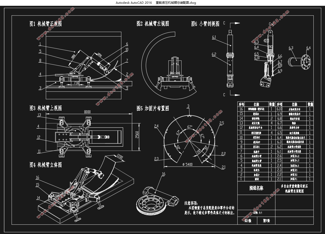
本文以隧道加固技术为研究背景,设计了一种多自由度重载搬运机械臂。通过对机械臂操作环境以及操作对象的深入研究,根据机械臂作业要求,完成了对重载搬运机械臂的总体方案设计。内容包括对机械臂搬运流程的设计,自由度的设计,总体机构的设计以及其运动分析。在设计过程中主要应用了三维建模技术,参数化设计方法,机器人学方法,动力仿真技术。首先通过Solidworks三维建模技术对机械臂进行了基本的结构设计,而后通过参数化设计方法,即Adams参数化设计功能对机械臂虚拟样机进行了迭代仿真,得到机械臂的最优参数,进而得到机械臂各个杆件的参数。在得到机械臂的最优参数后,对其进行了正运动学分析以及逆运动分析。正运动分析得到其运动学方程,逆运动分析实现了对机械臂的运动轨迹规划以及其运动中的关节角变化量。最终通过Adams的动力仿真技术,验证了逆运动学分析的结论,同时对其进行了干涉检查,完成了对机械臂的运动轨迹修正,并得到了机械臂在工作过程中各主要驱动元件所需的力变化图。 [资料来源:THINK58.com]
关键词:重载机械臂;液压;隧道施工;运动分析;动力仿真
Summary
With the rapid development of construction and construction in China in recent years, multi-degree-of-freedom heavy-duty manipulators emerged as the times require. They have an irreplaceable role in the construction and maintenance of bridges, roads and tunnels. The application of heavy-duty manipulators in China is coming. The more extensive. At the same time, the development of the manufacturing industry and the continuous advancement of hydraulic technology have further accelerated the development of heavy-duty robotic arms.
Based on the research of tunnel reinforcement technology, this paper designs a multi-degree-of-freedom heavy-duty handling robot arm. Through the in-depth study of the operating environment of the robot arm and the operation object, the overall design of the heavy-duty handling robot arm was completed according to the requirements of the robot arm operation. The content includes the design of the robotic arm handling process, the design of the degree of freedom, the design of the overall mechanism and its motion analysis. In the design process, three-dimensional modeling technology, parametric design method, robotics method and dynamic simulation technology are mainly applied. Firstly, the basic structure design of the manipulator is carried out by Solidworks 3D modeling technology. Then the parametric design method, namely the Adams parametric design function, is used to simulate the virtual prototype of the manipulator, and the optimal parameters of the manipulator are obtained. The parameters of each arm of the robot arm. After obtaining the optimal parameters of the manipulator, positive kinematics analysis and inverse kinematic analysis were performed. The forward motion analysis obtains its kinematics equation, and the inverse motion analysis realizes the trajectory planning of the manipulator and the amount of joint angle change in its motion. Finally, the conclusions of the inverse kinematics analysis were verified by Adams's dynamic simulation technology. At the same time, the interference check was performed, and the trajectory correction of the mechanical arm was completed, and the main driving components required by the mechanical arm during the working process were obtained. The force change diagram. [资料来源:http://THINK58.com]
Key words: heavy-duty manipulator; hydraulic; tunnel construction; motion analysis; dynamic simulation
2.1机械臂操作环境及其特性研究
2.1.1 工作环境尺寸参数
隧道参数尺寸如图所示:
隧道内径D=5400mm,轨道面弦高S=800mm,轨道车平台高度H=1000mm
2.1.2 操作对象尺寸参数
加固板一共4种类型,分别按1/2/3/4进行排序
公共属性:
材料:热轧板
参数尺寸:板宽均为B=1200㎜,厚度K=32㎜,弯曲半径R=2700㎜
[来源:http://www.think58.com]


目录
第1章绪论 6
1.1 本课题研究背景和意义 6
1.2 国内外机械臂研究现状 7
1.2.1国外机械臂研究现状 7
1.2.2国内机械臂研究现状 7 [来源:http://think58.com]
1.3 课题研究的主要内容 8
第2章机械臂总体方案设计 9
2.1机械臂操作环境及其特性研究 9
2.1.1 工作环境尺寸参数 9
2.1.2 操作对象尺寸参数 9
2.1.3机械臂工作环境及操作对象特性分析 10
2.2 机械臂工作流程分析 11
2.2.1机械臂作业任务介绍 11
2.2.2 机械臂搬运次序方案分析 12
2.3机械臂总体机构分析与建立 13
2.3.1机械臂自由度的分析与建立 13
2.4机械臂驱动方式选择 16
2.5机械臂控制方式选择 16
2.6 本章小结 16
第3章机械臂结构设计 17
3.1机械手结构设计 17
3.1.1机械手结构设计的理论依据 17
3.1.1机械手结构设计具体方案 17
3.2基座结构设计 19
3.2.1基座结构设计的理论依据 19
3.2.2基座结构设计的具体方案 20
3.3 机械臂大臂和小臂设计 22
3.3.1机械臂大臂和小臂设计的理论依据 22
3.3.2机械臂大臂和小臂方案设计 22
3.4 机械臂整体支腿设计 25
3.4.1机械臂整体支腿设计的理论依据 25
3.4.2机械臂整体液压支腿方案设计 26
3.5 本章小结 26
第4章基于Adams的机械参数优化 28
4.1机械参数优化流程 28
4.2 机械参数优化目标 28
4.2.1参数优化的理论依据 28
4.3 机械参数优化目标 30
4.3.1参数优化的理论依据 30
4.3.2为构件施加约束,驱动,定义力 31
4.3.3对虚拟样机进行参数化 32
4.3.4设计变量数值设置 35
4.4 参数化虚拟样机正确性验证 36
4.3.4验证的目的和方法 36
[来源:http://think58.com]
4.3.4验证的具体过程 36
4.4 低精度迭代仿真 37
4.4.1低精度迭代仿真的目的 37
4.4.2低精度迭代仿真具体实施过程 37
4.5 高精度迭代仿真 43
4.6 本章小结 44
第5章机械臂正运动分析 45
5.1 建立机械臂D-H参数 45
5.1.1建立机械臂坐标系 45
5.1.2建立D_H参数 46
5.2 求解机械臂运动学方程 46
5.2.1建立机械臂运动学方程 46
5.2.2求解机械臂的齐次坐标变换矩阵 47
5.3 本章小结 49
第6章机械臂逆运动分析 50
6.1 机械臂执行末端运动轨迹规划 50
6.1.1拿取加固片过程运动轨迹规划 50
6.1.2初次定位加固片过程运动轨迹规划 51
6.1.3完成定位加固片过程运动轨迹规划 53
6.2 机械臂逆运动方程求解 57 [版权所有:http://think58.com]
6.2.1拿取加固片过程各个关节角变量求解 57
6.2.2初次定位加固片过程各个关节角变量求解 58
6.2.3完成定位加固片过程各个关节角变量求解 58
6.2.4各液压缸伸缩长度计算 59
6.3 本章小结 62
第7章基于Adams的机械臂动力仿真 63
7.1建立机械臂Adams虚拟样机 63
7.1.1建立工作环境 63
7.1.2对构件添加属性 63
7.1.2对构件添加约束和驱动 64
7.1.3建立各个液压缸添加运动驱动函数 65
7.2机械臂干涉检查及运动轨迹修正 68
7.2.1机械臂干涉检查 68
7.2.2机械臂运动轨迹修正 69
7.2.3执行末端运动轨迹图 72
7.3 对逆运动学分析结果进行验证 73
7.4 关键液压缸的受力变化图 74
7.4 本章小结 76
致谢 77
[资料来源:www.THINK58.com]
参考文献 79
附件1机械臂装配总图……………………………………………………………. 80
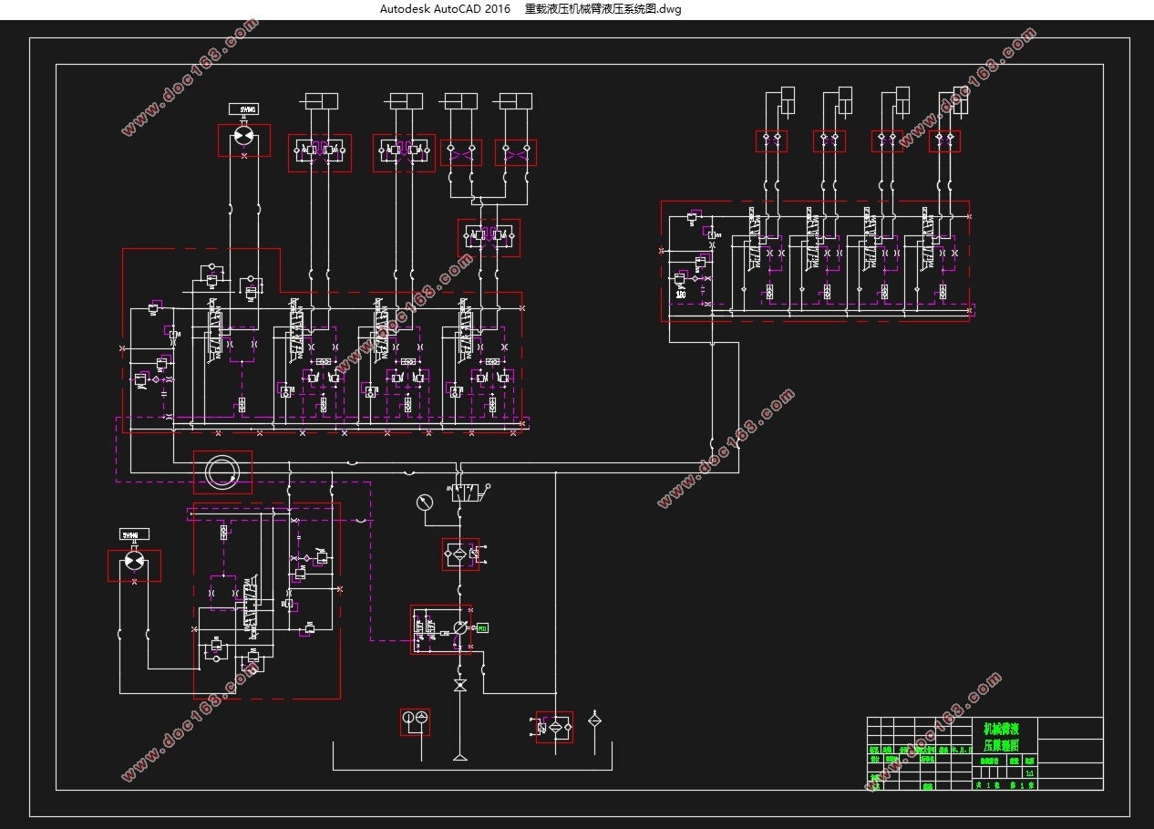
附件2机械臂液压系统图……………………………………….………………. 81
[资料来源:http://think58.com]
