数控钢套割断机尾座及液压设计(含CAD零件装配图)

1.无需注册登录,支付后按照提示操作即可获取该资料.
2.资料以网页介绍的为准,下载后不会有水印.资料仅供学习参考之用.
密 惠 保
数控钢套割断机尾座及液压设计(含CAD零件装配图)(论文说明书7800字,外文翻译,CAD图9张)
摘要
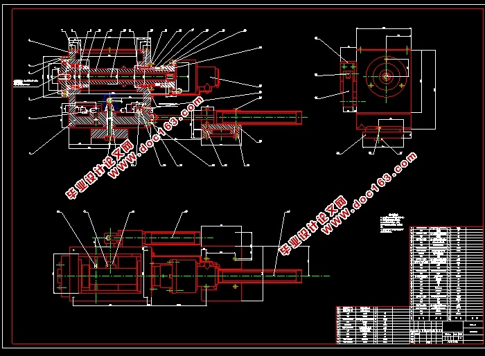
数控钢套割断机是专门用于加工钢套的数控机床,该机床为批量生产设备,为满足生产的需求,数控钢套割断机的加工动作应快速完成以增加钢套的产量。数控钢套割断机在生产过程中先是由床头夹具夹紧工件的一端,接着尾座靠近工件并夹紧工件的另一端,当工件被夹紧后开始加工工件,在此工程中全部动作都为自动完成。尾座自动化是增加钢套产量的重要一环,在原有的普通机床基础上,对机床的尾座进行改进,在尾座中增加液压系统,使数控钢套割断机尾座能够实现自动化。数控钢套割断机尾座由尾座夹具、尾座锁紧装置和尾座移动装置三部分组成,这三部分装置分别由三个液压缸作为动力装置,其中两个为行程液压缸一个为推力液压缸。通过液压缸推拉尾座箱体以实现尾座的自动移动,通过液压缸推动偏心轴以实现尾座的自动锁紧,通过推力液压缸推动尾座推杆使尾座自动夹紧工件。本文将尾座的自动到位设计、尾座锁紧装置的设计以及尾座夹具自动夹紧装置的设计的详细过程叙述出来,还会对尾座的液压系统设计进行详细说明。
关键词:尾座;液压系统;自动化
ABSTRACT
[资料来源:THINK58.com]
The CNC steel sleeve cutting machine is a CNC machine tool specially designed for processing steel sleeves. The machine is a mass production equipment. In order to meet the production requirements, the CNC steel sleeve cutting machine machining operations should be completed quickly to increase the output of steel sleeves. In the production process, the CNC steel sleeve cutting machine first clamps one end of the workpiece by a bedside clamp, and then the tailstock approaches the workpiece and clamps the other end of the workpiece. When the workpiece is clamped, the workpiece starts to be machined. In this project, all actions are performed. For automatic completion. Tailstock automation is an important part of increasing the output of steel sleeves. Based on the existing common machine tools, the tailstock of the machine tool is improved, and the hydraulic system is added to the tailstock to enable the tailstock of the CNC steel sleeve cutting machine to be automated. The tailstock of the numerically controlled steel sleeve cutting machine is composed of a tailstock clamp, a tailstock locking device and a tailstock moving device. The three parts are respectively powered by three hydraulic cylinders, and two of them are stroke hydraulic cylinders. Hydraulic cylinders. The tailstock box is pushed and pulled by the hydraulic cylinder to realize the automatic movement of the tailstock, and the eccentric shaft is pushed by the hydraulic cylinder to realize the automatic locking of the tailstock, and the tailstock push rod is pushed by the thrust hydraulic cylinder to automatically clamp the tailstock to the workpiece. This paper describes the details of the automatic design of the tailstock, the design of the tailstock locking device, and the design of the tailstock clamp automatic clamping device. The hydraulic system design of the tailstock will also be described in detail.
[资料来源:http://www.THINK58.com]
Key Words:Tailstock;Hydraulic system;Automation
总体方案
根据数控钢套割断机的工作原理,数控钢套割断机尾座由尾座自动到位装置、尾座自动锁紧装置、尾座自动夹紧装置以及液压系统构成。尾座通过液压缸的作用使得尾座的移动、夹紧、锁紧都能自动的完成。自动化的尾座可以减少机床操作者的工作量,降低人为因素的精度误差,提高生产效率。
以下是尾座各部分的设计方案。
2.1尾座自动到位
尾座自动到位由一个行程液压缸来实现尾座的移动,尾座放置于车床导轨上,尾座能够在导轨上移动,实现自动到位。根据数控钢套割断机的设计,要求尾座的位移为250mm,将液压缸固定于固定体中,液压缸位于尾座的后面并且和尾座在同一水平面上,液压缸活塞杆与尾座的底座用螺栓固定在一起,尾座的移动随着液压缸活塞杆的伸缩来实现
2.2尾座锁紧
尾座的锁紧由一个行程液压缸和一个滑块连杆机构来实现。
液压缸固定在固定座上,固定座固定在尾座箱体壁外侧上,液压缸的活塞杆连接一组连杆,连杆与偏心轴连接,当偏心轴的转动后,套在偏心轴上的连接套被抬升,与连接套一起连接的螺栓随着偏心轴抬升,当螺栓被抬升后,套在螺栓上的移动块与车床床体紧密贴合,至此实现尾座的锁紧。为保证精度,移动块在不锁紧的情况下应不能出现晃动的情况,并且为了使得锁紧程度更强,因此在移动块与连接套之间的螺栓段中套入弹簧。
[资料来源:http://think58.com]
其中连杆采用平面滑块连杆机构,液压缸的活塞杆与滑块连接,通过活塞杆的伸出与缩回来带动滑块沿水平面移动,从而带动偏心轴的转动实现尾座的自动锁紧
2.3尾座锁紧
尾座的夹紧由一个推力液压缸和一根尾座芯轴来实现。
由于尾座在夹持工件时位移小而推力大,因此选用推力液压缸作为尾座夹紧的动力源,将其与尾座芯轴的连接。当液压缸的活塞杆伸出时,尾座芯轴随着活塞杆的伸出而向外伸出推动芯轴前端的夹紧部件,使夹紧部件伸开来与钢套的内壁紧密接触,以此达到对钢套的夹紧作用,在对钢套进行割断作业时,尾座芯轴随着钢套的转动而转动。当液压缸的活塞杆缩回时,夹紧部件的夹持件缩回,夹紧装置就会松开工件,这就通过液压缸的作用实现了尾座的自动加紧功能
[资料来源:http://www.THINK58.com]


目录
摘要 I
ABSTRACT II
1. 绪论 1
1.1 选题背景和写作意义 1
1.2国内外研究现状及应用前景 1
2. 总体方案 3
2.1尾座自动到位 3
2.2尾座锁紧 3
2.3尾座锁紧 4
2.4液压系统 5
3. 尾座自动到位装置设计 6
3.1受力分析 6
3.2液压缸固定座设计 6 [版权所有:http://think58.com]
4. 尾座锁紧装置设计 8
4.1受力分析 8
4.2连杆机构设计 8
5. 旋转装置设计 11
6. 偏心轴校核 12
6.1受力分析 12
6.2强度校核 13
7. 液压系统设计 16
7.1设计要求 16
7.2负载和速度分析 16
7.3拟定液压系统 18
7.4计算液压系统主要参数 18
7.5拟定液压系统 20
7.6液压元件的计算和选择 22
7.7系统油液温升验算 24
7.8液压系统的性能估算 25
7.9控制系统 25
8. 结论 27
参考文献 28
附录一 外文译文 29
附录二 外文原文 36
致 谢 42
[来源:http://www.think58.com]
