
关节式钻床设计(含CAD零件装配图,SolidWorks三维图)
1.无需注册登录,支付后按照提示操作即可获取该资料.
2.资料以网页介绍的为准,下载后不会有水印.资料仅供学习参考之用.
密 惠 保
关节式钻床设计(含CAD零件装配图,SolidWorks三维图)(开题报告,文献综述,外文翻译,论文说明书20000字,CAD图纸9张,SolidWorks三维图)
摘 要
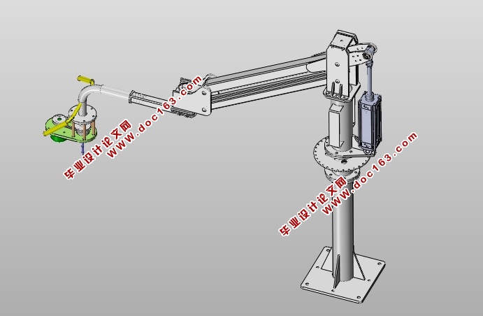
关节式钻床是能模仿人手和臂的某些动作功能,用以按照摆臂旋转的区域自行转动钻孔、攻牙的半自动化设备。它可代替普通台式钻床加工空间固定,不能灵活移动钻孔、攻牙的缺陷,能在摆臂旋转的360度的区域里面完成任意位置任意工件的钻孔、攻牙,因而广泛应用于机械制造、模具加工,锻造,冶金等等领域,在加工领域占据了越来越重要的位置。
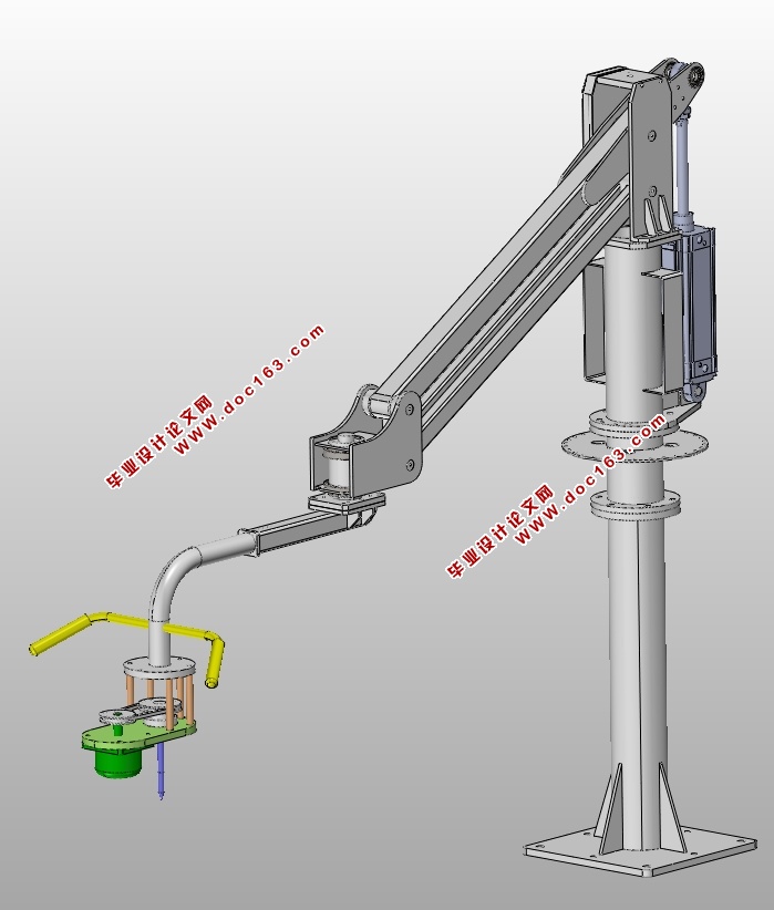
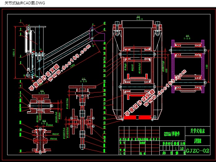
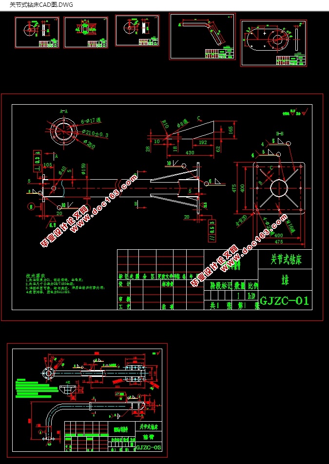
本文主要进行了关节式钻床的总体结构设计和气动设计。关节式钻床的机械结构由气缸、旋转关节和钻孔装置组成,可按预定轨迹运动,在任意的有效区域内实现对工件的钻孔,攻牙的操作。气动部分的设计主要是选择合适的控制阀,设计合理的气动控制回路,通过控制和调节气缸压缩空气的压力、流量和方向来使气动执行机构获得必要的力、动作速度和改变运动方向,并按规定的程序工作。
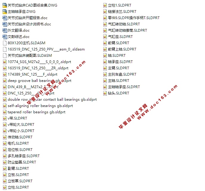
本文详细介绍了运用SolidWorks软件(3D 机械设计软件的标准)进行关节式钻长的设计。由于SolidWorks软件无论对零件设计,还是对整个机构设计都起了一个模拟仿真的作用,在SolidWorks软件中,我们可以直观,清楚地了解整个设计的外形,运作甚至是材料的分析。借助SolidWorks,将产品更快地投入市场。SolidWorks 提供无与伦比的性能和价值,它是技术创新的领先者,并且还拥有最大的用户群。没有其他CAD 系统可以帮助您快速准确地完成产品设计工作。 [资料来源:http://THINK58.com]
本文先对SolidWorks软件作出简介,对此三维软件作出一系列的说明,而后对关节式钻床设备进行介绍,并结合SolidWorks软件,将二者融会贯通。通过SolidWorks软件设计,从二维的AUTOCAD零件图纸,到三维的SolidWorks整个设备,大大地提高了设计的效果和效率,避免了工程师们在现实中出现的错误,切切实实地展现出三维软件的强大性能。
关键词:关节式钻床;气缸;Silidworks;自由度。
absraote
Pneumatic manipulator is a automated devices that can mimic the human hand and arm movements to do something,aslo can according to a fixed procedure to moving objects or control tools. It can replace the heavy labor in order to achieve the production mechanization and automation, and can work in dangerous working environments to protect the personal safety, Therefore widely used in machine building, metallurgy, electronics, light industry and atomic energy sectors.
This article is mainly of the pneumatic manipulator the overall design, and pneumatic design. This mechanism of manipulator includes cylinders and claws and connectors parts, it can move according to the due track on the movement of grabbing, carrying and unloading. The pneumatic part of the design is primarily to choose the right valves and design a reasonable pneumatic control loop, by controlling and regulating pressure, flow and direction of the compressed air to make it get the necessary strength, speed and changed the direction of movement in the prescribed procedure work.
[资料来源:http://THINK58.com]
s. It can replace the heavy labor in order to achieve the production mechanization and automation, and can work in dangerous working environments to protect the personal safety, Therefore widely used in machine building, metallurgy, electronics, light industry and atomic .The principle, technical pare-maters, transmiting system and main parts structure of mincing ma-chine were introduced. The productingcapacity was analysed.Keywords Mincing machine Holds plate Cutting blade Transfer auger
This paper discusses the meat processing machinery - crusher working principle, main technical parameters, transmission system, the typical parts of the structure design and production capacity analysis.
Small twisted paper broken machine for ordinary home, not only can be used for minced meat, can also be used with crushed peanuts, crushed ice, spices and other food, small power requirements, powered by the motor drive, reasonable structure design, can meet the family kitchen generally meat food consisting mainly of minced required.
Key word: pneumatic manipulator;cylinder;pneumatic loop;Four degrees of freedom.
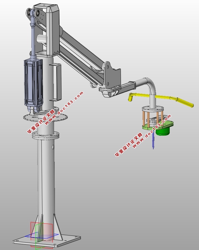
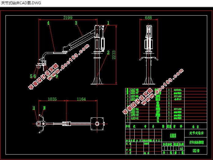
设计技术参数如下:
1、钻孔工件的重量:5Kg
2、自由度数:N个自由度
3、坐标型式:圆柱坐标
4、最大工作半径:2000mm
5、机身最大中心高:2300mm
6、主要运动参数:
手臂伸缩行程:1200mm 手臂伸缩速度:200mm/s
机身升降行程:120mm 机身升降速度:100mm/s
机身回转范围:0- 180° 机身回转速度:90°/s
本设计的关节式钻床完成各个运动的气缸只有完全伸出和完全缩回两个状态,选择两位五通换向阀控制各个气缸的运动方向,气缸的进出口回路各设置一个单向节流阀,通过控制进出口空气流量的大小来控制气缸执行器动力的大小和运动速度。设计中采用PLC控制关节式钻床实现各种规定的预定动作,既可以简化控制线路,节省成本,又可以提高劳动生产率。
目录
摘要 1
Abstract 2
第一章 绪论 3
1.1 课题的来源与研究的目的与意义.........................................................................4
1.2关节式钻床的方案分析.............................................................................................. 5
1.2.1 结构分析............................................................................................................6
[资料来源:THINK58.com]
1.2.2 机械结构总体方案与布局.........................................................................7
1.2.3课题研究的内容....................................................................................8
1.2.3.1 Solidworks设计基础....................................................................9
1.2.3.2 草图绘制.......................................................................................10
1.2.3.3 基准特征,参考几何体的创建.....................................................11
1.2.3.4 拉伸、旋转、扫描和放样特征建...................................................12
1.2.3.5 工程图的设计...............................................................................13 [资料来源:THINK58.com]
1.2.3.6 装配设计.......................................................................................14
第二章 机械结构的设计........................................... ..................................................15
2.1 气缸的选型计算 16
2.2 关节式钻床摆臂长度的设计 17
2.3 步进电机的选型计算 18
2.4 带传动的设计计算 19
第三章 关节式钻床各部分强度的校核 20
3.1轴承强度的校核 21
3.2摆臂方管强度的校核 22
3.3传动轴强度的校核 26
第四章 结构设计及三维建模......................................................................................27
4.1底部机架的三维建模...........................................................................................38
4.2摆动气缸的三维建模............................................................................................29
[资料来源:http://www.THINK58.com]
4.3步进电机的三维建模.............................................................................................30
4.4V带轮的三维建模...................................................................................................31
4.5关节式钻床的三维建模........................................................................................32
第五章 零件加工工艺流程图......................................................................................33
第六章 应用Solidworks软件对关节式钻床指定零件进行受力分析...................34
第七章 三维软件设计总结...........................................................................................35
结论 36
致谢 37
参考文献 38 [来源:http://think58.com]