三自由度全液压机械手结构设计(含CAD零件装配图)

1.无需注册登录,支付后按照提示操作即可获取该资料.
2.资料以网页介绍的为准,下载后不会有水印.资料仅供学习参考之用.
密 惠 保
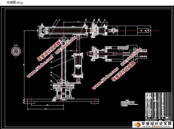
三自由度全液压机械手结构设计(含CAD零件装配图)(任务书,文献综述,设计说明书12800字,CAD图纸4张)
摘要
机械手是能复制相对于人的手臂的动作来取得固定的程序,或者自动操作物体设备的操作。为了人们的生产需要,机械手需要许多的工作设置,褚如手动和自动(包括单周期,单步骤,连续和自动返回到初始状态)的工作。在运动控制中,PLC可以用于控制一个线性运动或圆周性运动。所以,在使用PLC程序控制的,可以完成机械手应用程序的控制。这里的规模方案是指电磁阀动作的操作,每一个极限开关位置,周期的连续运转和精确性。关于液压驱动系统,为了避免过度使用三相异步电动机,而且它更可以提供过载保护。总体来说机械手,PLC,是一个集高效,安全,经济,实用的特点于一身的液压系统。
到目前为止,我主要介绍了设计进程开始具体工作:
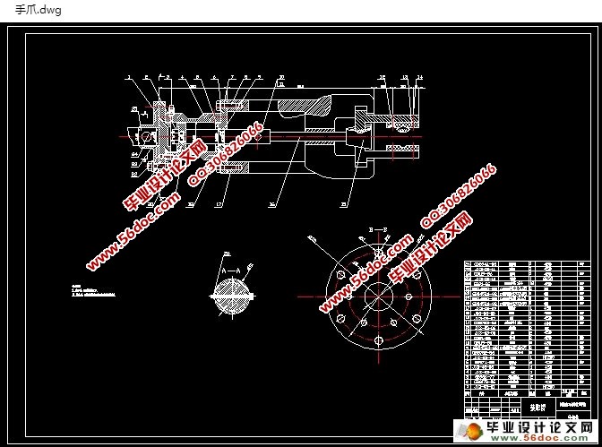
本设计内容包括:机械手的夹持机构设计,液压系统设计,PLC的软件设计,PLC的硬件设计。
机械结构是由机械手油缸,螺丝,导致管组成的液压执行器等机械装备,可以任意伸缩的伸缩缸机械手,用旋转圆筒转动手腕,用缸架转动柱,用升降油缸动作的机械手,在货架上立柱可以用PLC控制电路中使用横向移动油缸,用于FX2N PLC的类型,当连续按下启动键后,PLC程序中指定的控制电磁阀的开关来控制机机械手的各个动作循环,当你反复按下停止按钮时,机械手操作的几个周期结束之后会停止运动。
[来源:http://think58.com]
关键词:液压机械手,液压控制回路,PLC
Abstract
Handling robot can mimic some of the actions and arm function to obtain a fixed program, or equipment operation means moving object automatic operation. In order to meet production needs, the robot needs a variety of work settings, such as manual and automatic (including continuous, single-cycle, single step and automatically returns to its initial state) work. In the motion control, PLC can be used to control a circular motion or linear motion. Therefore, the use of PLC program control can be achieved robot control applications. Scale program to make the operation of the solenoid valve operation, each of the limit switch position, cycle-accurate and continuous operation. Hydraulic drive systems for vehicles, in order to avoid the use of three-phase asynchronous motors, it has the advantage of preventing overload. Overall, robot, PLC, by an efficient, safe, economical and practical features hydraulic system.
The design includes:Clamping mechanism designed robot, hydraulic system design, software design of PLC, PLC hardware design.
Mechanical structure robot tanks, screws, causing the hydraulic actuator tubes, machinery and equipment, retractable telescopic cylinders of the robot arm, wrist rotation with a rotating cylinder with cylinder rotary-column, with the lift cylinder operation of the robot, the column on the shelf PLC The control circuit traversing cylinders used for FX2N PLC type, press the start when continuous control solenoid valve switch PLC program to control various actions specified loop robot, when you repeatedly press the stop button, the robot operation Stop motion after the end of a cycle.
Keywords: robot, hydraulic control circuit, PLC


目 录
引言 1
第一章 手部的结构设计 3
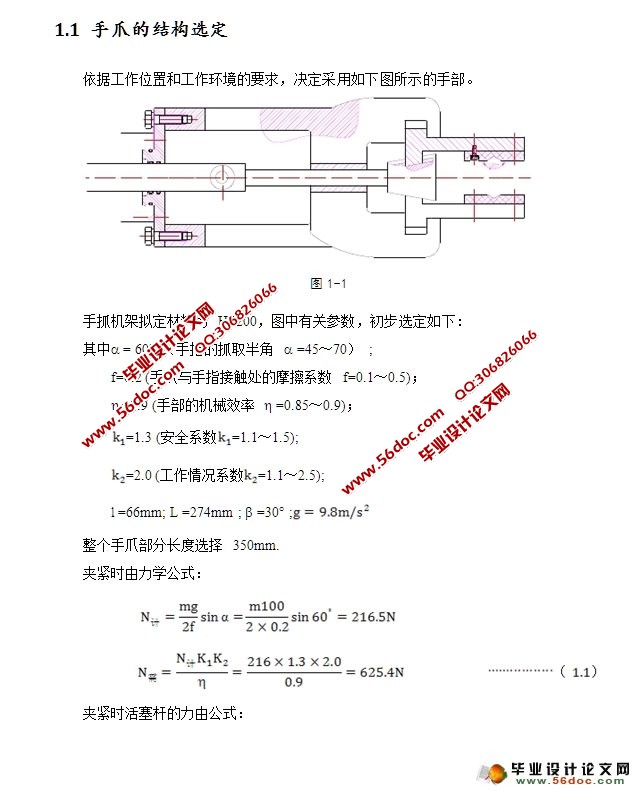
1.1 手爪的结构选定 3
1.2 液压缸的选用 4
1.2.1 液压缸内径的确定 4
1.2.2 液压缸外径的确定 4 [资料来源:http://THINK58.com]
1.2.3 钢筒壁厚校核 5
1.2.4 液压缸活塞杆的确定及校核 5
1.2.5 活塞的最大行程 6
1.2.6 钢筒底部厚度的确定 6
1.2.7 缸盖螺钉的计算 6
1.2.8 缸筒头部法兰厚度的确定 7
1.2.9 液压缸其他元件的确定 8
第二章 小臂的结构设计 9
2.1 小臂的结构初定 9
2.2 小臂受力分析 9
2.3 小臂液压缸的选定 10
2.3.1 小臂液压缸内径的确定 10
2.3.2 液压缸内径的确定 11
2.3.3 液压缸外径的确定 11
2.3.4 缸筒壁厚校核 12
2.3.5 液压缸活塞杆的确定及校核 12
2.3.6 活塞的最大行程 12 [版权所有:http://think58.com]
2.3.7 缸筒底部厚度的确定 13
2.3.8 液压缸流量的确定 13
2.3.9 缸盖螺钉的计算 14
2.3.10缸筒头部法兰厚度的确定 14
2.3.11 液压缸其它元件的确定 15
第三章 手臂支座的设计 16
3.1 支座材料的选定 16
3.2 支座结构的设计 16
第四章 手臂上下摆动的设计 17
4.1 手臂和手部的受力分析 17
4.2 手臂上下摆动液压缸的确定 17
4.2.1 液压缸内径的确定 18
4.2.2 液压缸外径的确定 18
4.2.3 缸筒壁厚的校核 19
4.2.4 液压缸活塞杆的确定及校核 19
4.2.5 活塞杆的最大允许行程 20
4.2.6 缸筒底部厚度的确定 20
[来源:http://think58.com]
4.2.7 缸盖螺钉的计算 20
4.2.8 缸盖头部法兰厚度的确定 21
4.2.9 缸筒与端部焊接 22
4.2.10液压缸其它元件的确定 22
第五章 手臂回转的设计 23
5.1 回转缸的确定 23
5.2 叶片螺钉的选择 24
5.3 缸盖螺钉的计算 25
5.4 液压缸其它元件的确定 25
第六章 底座的设计 26
6.1 底座材料和尺寸的确定 26
6.2 底板螺钉的确定 26
6.2.1 受翻转力矩的螺栓组联接 27
6.2.2 缸盖螺钉的计算 27
第七章 液压系统传动方案的确定 28
7.1 各液压缸的换向回路 28
7.2 调速方案 29
7.3 系统的安全可靠性 29
7.4 液压系统的合成和完善 29
第八章 计算和选用液压元件 29
8.1 阀的种类和功用 29
8.2 拟定液压系统 30
8.3 油泵的选择 31
8.4 液压系统中的辅助装置 32
第九章 液压系统原理图 33
总 结 35
参考文献 36
致 谢 37 [来源:http://www.think58.com]
