小汽车举升机的三维设计(含CAD图,SolidWorks三维图)

1.无需注册登录,支付后按照提示操作即可获取该资料.
2.资料以网页介绍的为准,下载后不会有水印.资料仅供学习参考之用.
密 惠 保
小汽车举升机的三维设计(含CAD图,SolidWorks三维图)(任务书,文献综述,设计说明书9000字,CAD图纸13张,SolidWorks三维图)
摘 要
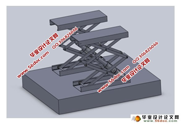
小汽车举升机的三维设计是在认真思考了现有的各种起重设备和实际工作条件的情况下,从而进行的举升机的剪式结构的设计。在设计中完全考虑到安全和使用要求,结合计算机技术来优化举升机设计,以实现不同客户需求,不同小汽车型号的需求。
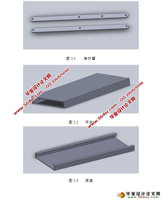
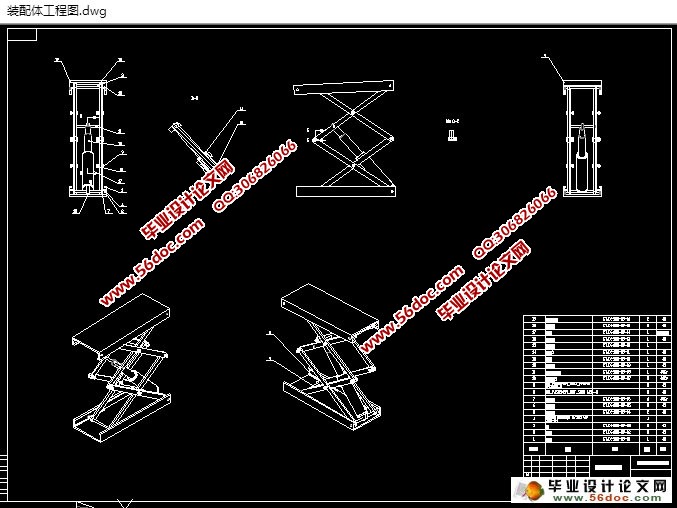
经过初期的结构设计,参数设置以及力学分析给出整体的合理型式,再通过SolidWorks建立各零部件的三维建模,并结合虚拟装配,,最后举升机工作过程的仿真是通过SolidWorks的运动仿真功能来实现,以检验整套装置的合理性和灵活性。
关键词: 三维设计; 剪式; 汽车举升机; SolidWorks
Abstract
Three-dimensional design of the car lift is seriously considering lifting equipment under actual working conditions and the existing design of the scissor lift structure thus conducted. Fully taken into account in the design of the safety and use requirements, combined with computer technology to optimize the lift design to fulfill customer needs, different needs of different car models. [资料来源:http://THINK58.com]
By the preliminary structural design, parameter setting and the mechanical analysis gives a whole reasonable type. Then use SolidWorks establish various parts of the three-dimensional modeling, and realize the Virtual Assembly. Finally, though the motion simulation function of SolidWorks realize the working process simulation of Lifter, to test the rationality, flexibility of the entire device.
Key words: Three-dimensional design; Scissor structure; car repair Lifter; Solid Works;
某汽车维修4s店进行汽车维修养护时,需要将小型汽车举升起来,维护汽车底盘及轮胎等部分。本设计就是要设计一台汽车举升机,举升重量大约为3000~4000kg,要求运用solid works软件进行三维建模和模拟仿真。
有关本课题的工艺参数:
设计一台小剪式汽车举升机,参数如下:
最大举升高度: 1800mm;
额定举升重量: 4000 kg;
底盘距离地面距离: 110mm;
整个过程上升时间: 50S;
整个过程下降时间: 40S;
要求具有可靠的锁止装置;
2.2 结构的选择
由前言部分可知道,现在的举升机主要有如下几种:单柱和双柱式,四柱型,剪式和地沟式,而剪式举升机是现在的应用主流,故本设计采用剪式举升机的结构。根据设计方案,举升机是专为满足汽车修理厂维修车辆底盘和轮胎,以满足要求,结构设计举升机必须是合理的。所述剪式举升机属于该类举升机,一些支撑臂结构的基本支持平台,以确保整套装置的运动,各处的连接采用铰接。
[资料来源:http://www.THINK58.com]


目 录
第一章绪论 1
1.1选题的背景 1
1.1.1 举升机的发展 1
1.1.2 计算机辅助设计的发展 2
1.2选题目的及其意义 3
第二章举升机的结构设计 5
2.1设计任务 5
2.2结构的选择 5
2.3 结构尺寸的确定 7
2.3.1 平台结构 7
2.3.2 支撑臂长度的确定 8
2.4连接结构设计 8
2.4.1 连接方式的选择 8
2.4.2 材料选择 9 [资料来源:http://www.THINK58.com]
2.5 重量计算 9
第三章举升机的力学性能分析 11
3.1 支撑臂的力学分析 13
3.2 各部件的强度校核 17
3.2.1 上滑轮轴的校核 18
3.2.2 支撑臂的强度校核 19
第四章举升机的运动分析 26
第五章模型的建立 28
5.1 支架部分建模 28
5.2 液压系统 30
总 结 33
参考文献 34
致谢 35
[资料来源:http://think58.com]
