压力机和垫板间夹紧装置的设计

1.无需注册登录,支付后按照提示操作即可获取该资料.
2.资料以网页介绍的为准,下载后不会有水印.资料仅供学习参考之用.
密 惠 保
摘 要
本文介绍了一种新型的压力机与垫板间快速夹紧装置。分析了该装置的工作原理和液压控制原理和电器控制原理。(毕业设计网 )
在现代化的生产实际中,压力机与垫板之间的夹紧装置还是传统的手动夹紧装置。不仅耗时费力,而且已经远远不能满足现代化生产的需要,因而急需对其进行改造。
压力机与垫板间的快速夹紧设计就是应现代化生产的需要而研究设计的。该设计包括机械夹紧装置的设计,液压控制系统的设计,以及电气控制系统的设计。将机-电-液技术结合起来,实现快速夹紧。
压力机与垫板间快速夹紧装置主要由机械夹紧装置、液压控制系统、电气控制系统组成。它以机械夹紧装置为主要的夹紧执行元件。通过螺杆与螺母之间的螺旋传动实现夹紧、放松操作,并要求螺杆自锁。液压缸活塞杆的伸缩,使机械夹紧装置摆动,实现抽出垫板的目的。液压缸、液压马达的动作控制由液压系统实现。在液压系统中,采用了电磁换向阀和压力继电器。电磁换向阀和压力继电器的控制,由电气控制系统实现。在电气部分,采用了PLC控制,这样,整个装置的控制可靠性提高,通用性更好,操作更方便。
本设计融合了机-电-液一体化的设计理念,寻求更为有效的设计理论和方法来实现压力机与垫板的快速夹紧。该夹紧装置实现了设计目标,具有较高的自动化程度,运行稳定可靠,性能价格比较高,非常适合于现代化生产实际的需要。因此,该产品的推广具有十分广阔的前景。 [资料来源:http://www.THINK58.com]
关键词:夹紧装置;液压系统;电气控制;机电一体化。
[版权所有:http://think58.com]
Abstract
[资料来源:www.THINK58.com]
Design of The Clamping Device Between The Press and Backing Board
Abstract
This paper introduces a new type of fast clamping device between the press and the space block. It also analyzes the working principle and the hydraulic and the electrical principle for this kind of trigger equipment.
At present, in the practice of the moderation production, the clamping device between the press and the space block is still controlled by handed clamping equipment, it not only costs much time and labour power, but also can not meet the need of moderation production. For these reasons, the traditional handed clamping should be improved.
The design of a new type of fast clamping device between the press and the space block is based the need of moderation production. It consists three parts, which are machinery clamping equipment, the design of hydraulic control system and the design of the electrical controlling. The integration of the machinery, electricity and hydraulic pressure brings about fast clamping device.
There are three important parts: the fast clamping device, the hydraulic controlling system and the electrical controlling system. The machinery fast clamping is the most important clamping actuating mechanism. Through the spiral movement between the clamping device, the lead-screw and the nut, it realizes the clamping movement and disengagement , it also must has self locking.
The shank of the piston of the hydraulic presser has the movement of elongation and drawing back, in this way, we can realize oscillatory movement of the machinery, and get out the space block. The movement of the hydraulic presser and the hydraulic motor is controlled by the hydraulic control system. In the hydraulic system, the controlling of the solenoid operated direction vale and the pressure switch is realized by the electric automation.
The application of the PLC improves the reliability of the whole set, and makes the compatibility better and the controlling of the set much convenient.
This design consists the theory of the mechatronics, we want to find a much better designing theory and method to realize the fast clamping between the press and the space block. This fast clamping device brings about the target of this design, it has a high level of the automation and the operating is reliable. And what is more, the performance index is high. This device is much suited the need of the modernization production, so it has a broad prospect of promotion.
Key Words: clamping device, hydraulic system,electric control,mechatronics. [资料来源:THINK58.com]
传统的压力机与垫板间的夹紧机构采用手动操作,这在现代化生产实际中,已远远不能满足自动化生产的需要。
现代化的机械设备的控制技术手段是多种多样的,电器方法、机械方法、液压方法、电气液压方法以及气动方法等等,均可以用来实现自动控制。其中,机-电-液一体化设计已成为当代机械工业技术和产品发展的主要趋向,沿用已久的分工脱节,各管一段的设计方法,不仅耗时,而且难以获得一体化系统的最佳设计结果。
本设计引入了机、电、液一体化系统的设计理念,寻求有效的设计理论和方法来实现压力垫板夹紧的自动控制。
机械装置设计的重点是利用螺旋传动实现螺杆的上升、下降。因此,螺杆设计是本设计机械部分的核心。要求齿轮啮合传动安全、可靠、效率高,螺杆与螺母的传动能够自锁,有安全保障。
螺杆由45号钢调质处理,再对其进行淬火处理,使螺杆的强度与硬度提高。由于螺杆在本设计中的重要作用,决定了螺杆的寿命是本设计成败的重要标志。设计时,充分考虑了螺杆的强度和机械自锁,必须保证螺杆在任意位置能够自锁,才能使整个夹紧装置安全、可靠。尤其在螺杆及整个夹紧装置摆出一定角度,以使工人取出垫板时,不但要保证液压系统能够自锁,而且要求螺杆也要自锁。否则,夹紧装置失效,将造成极坏的后果。在设计的过程中,还考虑了许多的实际问题,如为给压力继电器提供有效的压力发讯信号,在螺杆的特定位置增加了圆环-半圆环结构,由螺栓联结,在螺杆轴向下降、放松垫板时,放松到位后,圆环-半圆环结构与螺母接触,压力继电器得到发讯信号作用,螺杆停止下降,放松到位。 [版权所有:http://think58.com]
圆环-半圆环结构在本设计中还有其他应用,除与螺母接触使压力继电器发讯之外,还被加在螺母上,作用相当于一个挡圈,防止齿轮由于重力而脱离螺母。
液压缸与液压马达的驱动控制由液压系统控制,在液压系统中应用了电磁换向阀与压力继电器。电磁换向阀与压力继电器和电动机的控制均由电气控制系统实现。
整个装置组成简单,结构精巧,控制方便,性能可靠,有很好的应用前景。
[版权所有:http://think58.com]
原始数据及设计要求
原始数据
(1) 夹紧头的夹紧力为10吨。
(2) 夹紧过程小于10秒钟。
(3) 夹紧的行程为20 mm。
(4) 系统压力为16 MP。
设计要求
(1)夹紧头夹紧后要求有自锁。
(2)整个夹紧装置中的八个夹紧头动作可以分别控制,以便于测试与检修。
(3)综合考虑机械、电气与液压控制的结合。
(4)在设计中要充分考虑使夹紧装置结构紧凑,美观,制造、维修成本低。 [资料来源:THINK58.com]
拟定设计方案
驱动机构包括液压马达,液压缸,单级齿轮传动1、2,螺旋-螺母传动。齿轮用键与螺母联结。具体用液压马达来带动齿轮1旋转,通过齿轮1、2的啮合传动将动力传递给自制螺母。将螺杆即夹紧头径向固定,使其通过与螺母的螺旋传动能够沿轴向上升、下降,从而实现夹紧或放松垫板的目的。通过液压缸活塞杆在垂直方向上的伸缩,实现夹紧装置的摆进、摆出。即液压缸的活塞杆伸出时,在液压力的作用下,推动整个夹紧装置摆出,并锁紧。反之,活塞杆缩回时,整个夹紧装置能够摆回,等待下一次的夹紧。整个系统实现夹紧-放松-摆进-摆出四个动作。
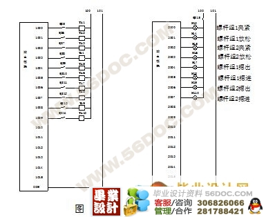
液压缸与液压马达的驱动由液压控制系统来实现,通过液压系统元件来实现液压缸的调速和液压缸与液压马达的换向。电动机与液压系统中的电磁换向阀和压力继电器的控制由电气部分实现,本设计引入了PLC来进行对电磁换向阀和压力继电器的控制,而电动机则用星-三角启动[1]。
2.3 确定系统的机械参数
滑动螺旋传动主要是承受转矩和轴向力。因轴向力的作用,螺旋副旋和面间的压强很大,而且相对的滑动速度又大,所以,其主要的失效形式是螺纹的磨损[5]。 [资料来源:http://www.THINK58.com]


目 录
1引言…………………………………………………………………………1
2机械设计与计算……………………………………………………………2
2.1 原始数据及设计要求………………………………………………2
2.2 拟定设计方案…………………………………………………………2
2.3 确定系统的机械参数…………………………………………………2
[版权所有:http://think58.com]
3 液压系统设计…………………………………………………………8
3.1 液压系统的方案设计…………………………………………………8
3.2 液压阀的选取…………………………………………………………9
3.3液压系统的参数设计和拟定液压原理图…………………………9
4 液压装置的结构设计……………………………………………………13
4.1 滤油器…………………………………………………………………13
4.2 油箱和压力表辅件…………………………………………………14
4.3 管接头…………………………………………………………………16
4.4 阀集成块………………………………………………………………16
5 电气控制…………………………………………………………………18
(毕业设计网 )
5.1 电气驱动………………………………………………………………18
5.2 星-三角起动的控制…………………………………………………18
5.3 PLC控制系统的设计………………………………………………18
设计总结…………………………………………………………………………27
参考文献…………………………………………………………………………28
致谢…………………………………………………………………………………29 [资料来源:http://think58.com]
[版权所有:http://think58.com]
