左支座零件的加工工艺及夹具设计(含CAD零件图夹具图)
1.无需注册登录,支付后按照提示操作即可获取该资料.
2.资料以网页介绍的为准,下载后不会有水印.资料仅供学习参考之用.
密 惠 保
左支座零件的加工工艺及夹具设计(含CAD零件图夹具图)(论文说明书9000字,CAD图纸9张,工艺卡,工序卡)
摘 要
本文设计的零件是“左支座”。首先要对零件加工工艺进行设计,从尺寸、结构、材料、技术要求等几个方面进行分析,将零件各个尺寸的加工难易程度进行归类,为后续具体的工艺制定提供依据;针对零件的尺寸和结构,再结合生产类型来选用合适的毛坯型式;确定毛坯之后需要初步对工艺路线进行确定,至少编制两条不同的工艺路线,进行对比后,从中选优;之后是选择合适的刀具、机床、夹具、辅具等;在工艺路线以及相关的刀、辅、量、夹等确定后,需要对加工的切削参数进行计算;最终完成工艺过程卡和工序卡。
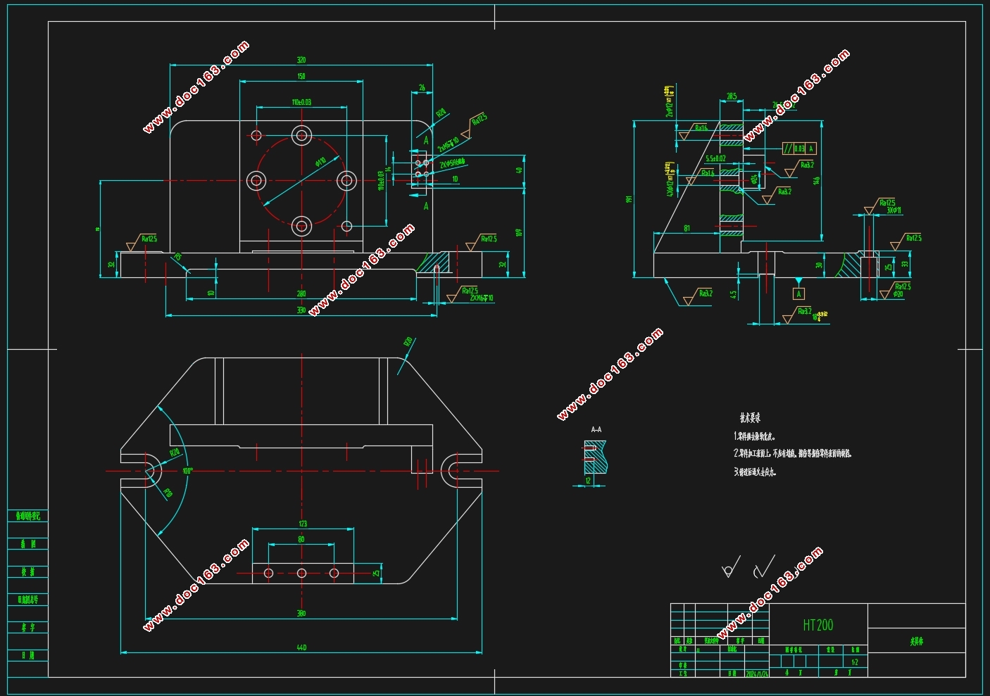
本文的第二个重点是夹具设计,夹具按大的类别分为通用夹具和专用夹具两种。通用夹具应用最为广泛,是按照机床尺寸设计的标准件,如分度头、三爪卡盘等,通用夹具多应用于小批量和单件加工。对于大批量生产,需要根据实际加工尺寸、机床、刀具进行特殊设计,以便达到加工效率的最大化。在本文中,介绍的是一种钻孔专用夹具,其是利用工件的一面两孔来限制自由度,利用螺母和构型压板来实现压紧,利用钻套对刀,从而达到加工要求。此次设计的夹具结构简单、制造成本低、具有专属性等特点,是工厂中常用的夹具设计类型。
关键词:左支座、工艺、基准、夹具
Abstract
The part designed in this article is the "left support". Firstly, it is necessary to design the machining process of the parts, analyze the dimensions, structure, materials, technical requirements, and other aspects, classify the machining difficulty of each size of the parts, and provide a basis for subsequent specific process formulation; Select the appropriate blank type based on the size and structure of the parts, combined with the production type; After determining the raw material, it is necessary to preliminarily determine the process route. At least two different process routes should be prepared and compared to select the best one; Next, choose suitable cutting tools, machine tools, fixtures, auxiliary tools, etc; After determining the process route and related tools, accessories, quantities, clamps, etc., it is necessary to calculate the cutting parameters for processing; Finally, complete the process card and process card.
[资料来源:http://THINK58.com]
The second focus of this article is fixture design, which is divided into two categories: general fixtures and specialized fixtures. Universal fixtures are the most widely used, designed according to the dimensions of machine tools, such as indexing heads, three jaw chucks, etc. Universal fixtures are mostly used for small batch and single piece processing. For large-scale production, special designs need to be made based on actual machining dimensions, machine tools, and cutting tools to achieve maximum machining efficiency. In this article, a special drilling fixture is introduced, which uses one side and two holes of the workpiece to limit the degree of freedom, uses nuts and configured pressure plates to achieve compression, and uses a drill sleeve to align the tool, thereby achieving machining requirements. The fixture designed this time has the characteristics of simple structure, low manufacturing cost, and exclusivity, making it a commonly used fixture design type in factories.
Keywords: left support, process, benchmark, fixture
零件图
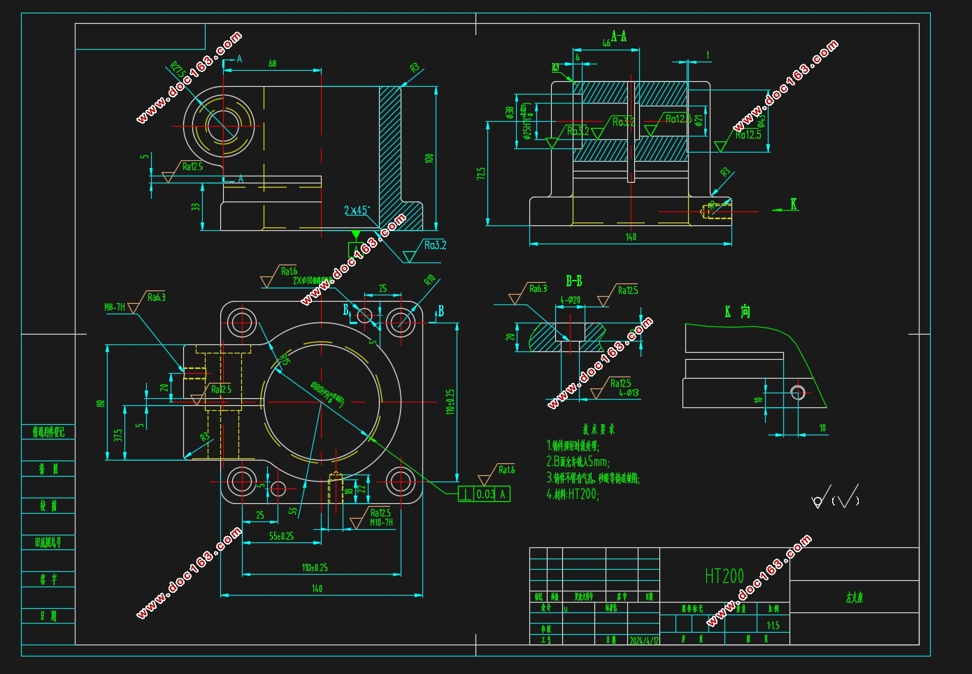
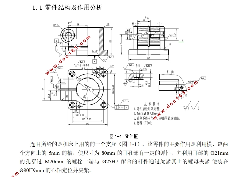
题目所给的是机床上用的的一个支座,该零件的主要作用是利用横、纵两个方向上的5mm的槽,使尺寸为80mm的耳孔部有一定的弹性,并利用耳部的Ø21mm的孔穿过M20mm的螺栓一端与Ø25H7配合的杆件通过旋紧其上的螺母夹紧,使装在Ø80H9mm的心轴定位并夹紧。
1.2 零件加工尺寸分析
从左支座结构图中可以看出,此件作为基础组件,其端面、内腔以及众多公差的精确尺寸需要精细处理。左支座包含多个加工平面,接下来逐一解析:
一、以中心定位的Ø80H9内孔加工面:这部分涉及的加工区域包括 Ø80H9孔的顶部平整区以及其边缘的内圆倒角,还有四个直径为Ø13mm的底座贯穿孔,四个Ø20的沉头螺钉孔,以及两个Ø10的锥形销孔。此外,底部带有M8-H7螺纹的Ø80H9毫米深度孔以及一条5毫米纵向槽口。首要加工的表面是Ø80H9,其中对Ø80H9孔轴线垂直度的要求极高,仅为0.03毫米。
二、基于Ø25H7毫米孔的加工中心:此组包含一个Ø21mm的通孔,两个Ø38的沉头螺钉孔和一个Ø43的沉头孔,底部带有M10-7H螺纹的Ø25H7毫米深度孔,以及一道5毫米宽度的横向槽。主要加工面仍然是Ø25H7。
总结起来,为了确保精度,可以采用分步策略,先加工一组,然后利用专用夹具精准定位,再进行另一组的加工,从而保证各部件间的精确位置一致性。
[版权所有:http://think58.com]
[来源:http://www.think58.com]
目 录
摘 要 I
Abstract II
引言 1
1、零件分析 2
1.1 零件结构及作用分析 2
1.2 零件加工尺寸分析 2
1.3 确定生产类型 3
2、零件的工艺设计 4
2.1 确定毛坯尺寸 4
2.2 确定主要表面加工方法 5
2.3 加工基准面的选择 5
2.4 制定工艺路线 6
2.5 工艺装备及机床的选择 8
2.6 切削用量的计算 9
2.6.1 粗、精铣A面切削用量 9
2.6.2 粗镗、半精镗、精镗孔φ80H9切削用量 10
2.6.3 粗宽5槽切削用量 11
2.6.4 钻扩铰φ25H7孔切削用量 12
2.6.5 钻攻M8孔切削用量 13
2.6.6 其他工序切削用量 14
3、夹具设计 15
[资料来源:http://www.THINK58.com]
3.1 铣槽夹具设计 15
3.1.1 问题的提出 15
3.1.2 工件在夹具中的定位 15
3.1.3 夹紧机构的设计 16
3.2 定位误差分析 17
3.3 夹紧力的计算 17
结 论 19
参考文献 20
致 谢 21
