后端盖零件编程及夹具设计(含CAD图,IGS,SolidWorks三维图,工艺工序卡)
1.无需注册登录,支付后按照提示操作即可获取该资料.
2.资料以网页介绍的为准,下载后不会有水印.资料仅供学习参考之用.
密 惠 保
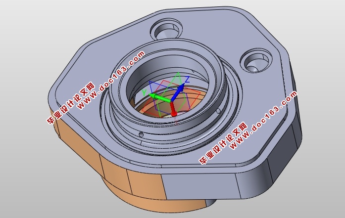
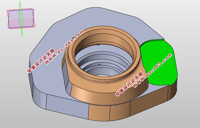
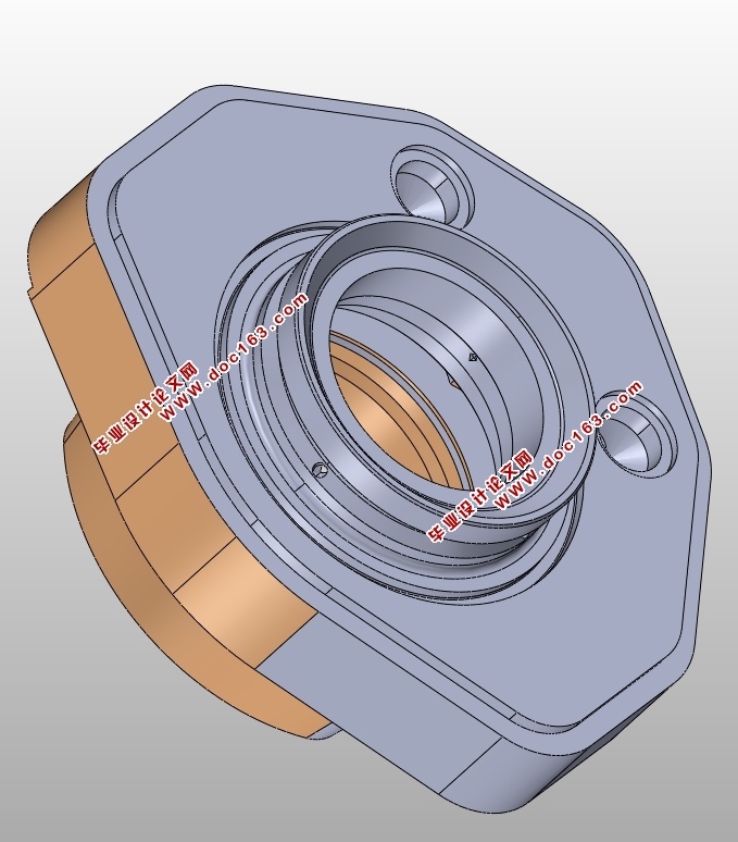
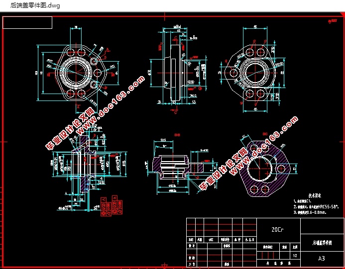
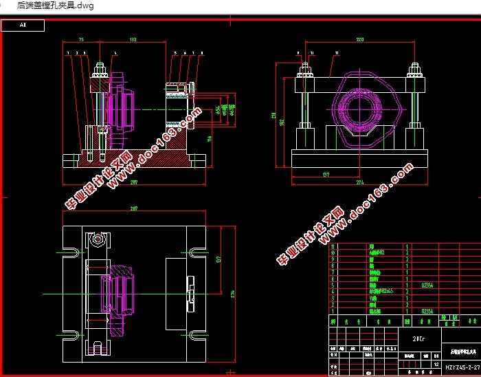
后端盖零件编程及夹具设计(含CAD图,IGS,SolidWorks三维图,工艺工序卡)(论文说明书12000字,CAD图纸4张,IGS,SolidWorks三维图,工艺卡,工序卡)
摘 要: 本篇毕业设计主要针对数控机床的加工及编程的介绍,对后端盖零件进行工艺性分析,包括加工工艺的选择和制定,还包括各零件的程序的手工编制。
文章的主要内容为后端盖零件的工艺分析和零件的手工程序编制。并在零件的手工编程中用到了G01 直线插补命令、G02/G03圆弧插补指令;G81钻孔;M98调用子程序指令等。
关键词:手工编程,指令,数控加工,工艺规程,定位误差,加工余量
Abstract:This graduation project mainly had the numerical control engine bed and the programming introduction, the ear components technological analysis craft parameter choice cutting tool choice, the components procedure manual establishment, the procedure simulation, the UG modelling and the entity simulation processing finally has made the design summary, the acknowledgment language, the reference tabulation and the appendix.
Article primary coverage for components craft analysis, components manual programming, but also has to make engineer's modelling and the entity simulation processing.Used the G02/G03 circular arc interpolation instruction in the components manual programming; G81 drill hole; M98 transfer subroutine instruction.
[来源:http://www.think58.com]
Key words:Manual programming;Circular interpolation instructions;drilled;subroutine programs.
[资料来源:THINK58.com]
[资料来源:THINK58.com]
 [来源:http://www.think58.com]
目 录
摘要 I
Abstract II
第一章 绪论 5
1.1 数控机床的介绍 6
1.2 数控编程 6
第二章 后端盖数控加工工艺分析 7
2.1 后端盖零件分析 8
2.2 刀具、量具的选择 9
2.3 编制加工工艺 10
2.4 手动编制程序 11
2.5 确定切削用量及基本时间 12
第三章 工件的手动编程 13
3.1 数控编程的定义及分类 14
3.1.1数控编程的定义 17
3.1.2数控编程的分类 17
3.1.3编程方法的选择 18
3.2 编程原点的确定 18
3.3 零件造型及加工 19
3.4 后端盖零件的仿真加工 20 [资料来源:THINK58.com]
第四章 镗孔夹具设计 20
4.1定位基准的选择 20
4.2定位元件的设计 20
4.3切削力及夹紧力的计算 22
4.4定位误差分析 23
4.5对刀块的设计 24
4.6夹紧装置的设计 26
4.7夹具设计及操作的简要说明 26
总结 26
参考文献 27
致谢 28
上一篇:发动机连杆加工工艺及夹具设计(含CAD零件图夹具图,工艺卡,工序卡)
下一篇:一种发动机缸盖单工序加工工艺及其夹具设计(含CAD图,工艺卡,工序卡)
