内齿轮加工工装夹具设计(含CAD零件图装配图)

1.无需注册登录,支付后按照提示操作即可获取该资料.
2.资料以网页介绍的为准,下载后不会有水印.资料仅供学习参考之用.
密 惠 保
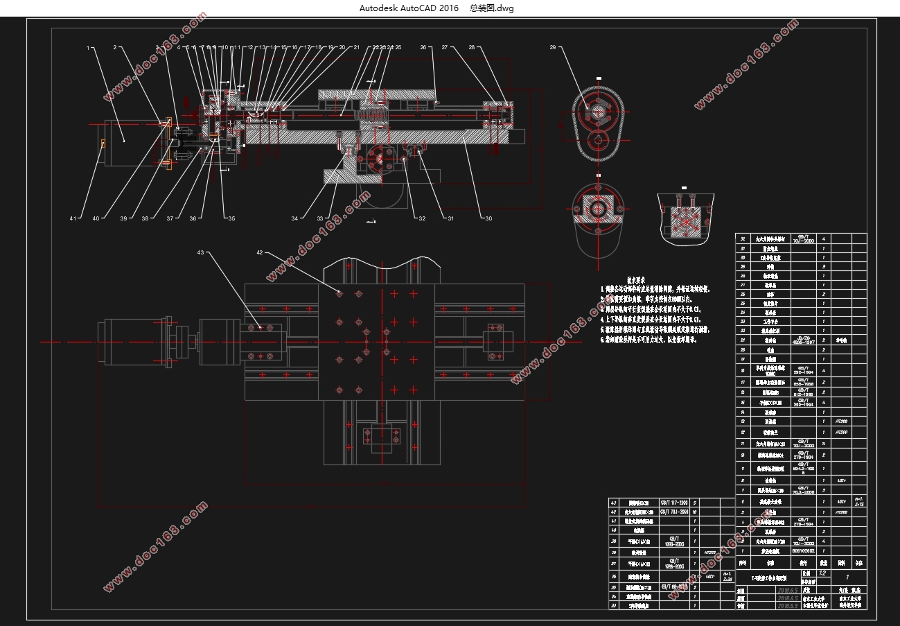
内齿轮加工工装夹具设计(含CAD零件图装配图)(任务书,开题报告,论文说明书9200字,CAD图4张)
摘要
工装夹具作为工艺装备中的重要组成部分,广泛应用于工业制造生产过程中,实现对工件的精准定位、快速夹紧和平稳传动,提供生产制造过程所必须的劳动条件,而且作为技术资料对于提高产品质量,降低人工成本和提高生产效率有着极其重要的影响。液压系统凭借其传动稳定、响应快速及体积紧凑等优点时常应用在工装夹具的设计中。
本文主要对待加工齿轮以及加工设备进行了分析,并按照工艺加工要求设计出针对该齿轮磨齿工序工艺加工过程中所需要的工装夹具,包含其设计理念,工作原理以及操作方法。针对齿轮加工过程需要定心定位要求,采用六爪卡盘作为夹紧装置,利用液压系统作为动力源,连杆作机械传动向下运动带动卡爪向中心运动,实现工件的定心定位以及夹紧。将多液压缸驱动简化为单液压缸驱动,平衡了各卡爪上的夹紧力,防止出现夹紧力不均而导致的偏心甚至工件变形的状况,同时简化了液压系统结构,降低了成本。
关键字:工装夹具 齿轮加工 磨齿 定位 夹紧
Fixture design for Internal Gear Machining
Abstract
As an important part of the technological equipment, the tooling fixture is widely used in the process of industrial manufacturing, realizing the precise positioning of the workpiece, fast clamping and stable transmission, providing the necessary labor conditions for the manufacturing process, and as a technical data to improve the quality of the product, reduce the labor cost and improve the production, having an extremely important impact. Hydraulic system is always used in fixture design because of its advantages of stable transmission, fast response and compact volume.
This article mainly deals with the analysis for the machined gear, and designs the fixture for the process of the gear grinding process according to the requirements of the process, including its design idea, working principle and operation method. The six-claw chuck is used as the clamping device and the hydraulic system is used as the power source. The connecting rod makes the mechanical drive downward movement to drive the claw movement to the center, so as to realize the positioning and clamping of the workpiece. The hydraulic cylinder drive is simplified as a single hydraulic cylinder drive, balancing the clamping force on each claw, preventing the eccentric and even workpiece deformation caused by uneven clamping force, and simplifying the structure of the hydraulic system and reducing the cost.
Key words: fixture gear machining grinding tooth location gripping
2.1 加工对象
2.1.1工件描述
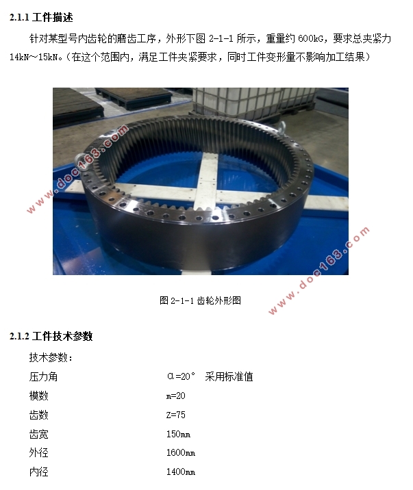
针对某型号内齿轮的磨齿工序,外形下图2-1-1所示,重量约600kG,要求总夹紧力14kN~15kN。(在这个范围内,满足工件夹紧要求,同时工件变形量不影响加工结果)
2.1.2工件技术参数
技术参数:
压力角 α=20° 采用标准值
模数 m=20
齿数 Z=75
齿宽 150mm
外径 1600mm
内径 1400mm
技术参数
SKMC-3000/20 数控成形磨齿机技术参数及描述: [资料来源:www.THINK58.com]
用于磨削圆柱(直/斜)齿轮,也可用于磨削其他可采用单分度磨削方法加工的工件。
标准设计:外磨头主电机功率:48kW
工作范围及技术参数
加工齿轮类别 圆柱齿轮
最大模数 30
最大磨削深度 75mm
螺旋角 ±45°
齿数 不限
最大齿轮宽度 800mm
X轴行程 1300mm [资料来源:http://think58.com]
Z轴行程 1100mm
砂轮直径 Φ280-400mm(与模数有关)
砂轮厚度 40-90mm(三副不同规格砂轮垫片)
砂轮主轴直径 Φ220mm
金刚滚轮尺寸 Φ160mm
最大冲程速度 4000mm/min
机床总功率 100kVA(380V 50Hz)
[版权所有:http://think58.com]


目录
摘要 I
Abstract II
第一章 绪论 1
1.1课题的背景与意义 1
1.2液压技术的特点 2
1.3 液压传动的基本原理和组成部分 2
第二章 加工对象分析 3
2.1 加工对象 3
2.1.1工件描述 3
2.1.2工件技术参数 3
2.2 加工设备 4
2.2.1设备描述 4
2.2.2技术参数 4
第三章 液压工作台工作原理分析 5
3.1 分析液压工作台传动系统 5
3.2制定液压工作台夹紧装置 5
3.2.1制定六爪卡盘作为工作台夹紧装置 5
3.3 制定液压系统工作原理 5
3.3.1系统内液压控制方案 6
3.3.2系统内工作流程 6
3.3.3液压动力源 6
3.3.4液压油净化过滤装置 6
3.4 液压泵站技术参数及要求 6
3.5 绘制工作台液压系统原理图 7
[资料来源:www.THINK58.com]
第四章 液压元件的计算选型与校核 8
4.1 设计计算 8
4.1.1 计算理论最大流量与理论最大压力 8
4.2液压缸 9
4.2.1 液压缸的选型 9
4.2.2 参数计算 10
4.3 液压阀 11
4.3.1 单向阀的选型 11
4.3.2 电磁换向阀的选型 11
4.3.3 溢流阀的选型 12
4.3.4 单向节流阀的选型 12
4.4冷却装置 13
4.4.1发热功率计算 13
4.4.2散热功率计算 13
4.5管路设计 14
4.6 液压辅件的选型 15
4.7 油箱的设计计算 15
4.8集成阀的设计 16
4.9系统压力损失 16
4.9.1沿程压力损失 17
4.9.2 液压阀元件的局部压力损失 18
4.9.3 工作台液压系统总压力损失 18
第五章 液压工作台的安装、调试、维护及经济论证 19
5.1液压工作台的安装 19
5.1.1技术准备 19
5.1.2 管道安装 19
5.1.3 液压元件的安装 19
5.2液压工作台的调试 20
5.2.1卡盘的调试 20
5.2.2液压系统泵站的调试 20
5.3液压工作台的维护 20
5.3.1卡盘的维护 20
5.3.2泵站系统的维护 20
5.4经济论证 20
第六章 总结和展望 22
参 考 文 献 23
致谢 25 [来源:http://www.think58.com]
下一篇:连杆的加工工艺及夹具设计(含SolidWorks三维图,PDF图)
