阀体的加工工艺编制及夹具设计(含CAD图,CAXA图纸,工艺卡)

1.无需注册登录,支付后按照提示操作即可获取该资料.
2.资料以网页介绍的为准,下载后不会有水印.资料仅供学习参考之用.
密 惠 保
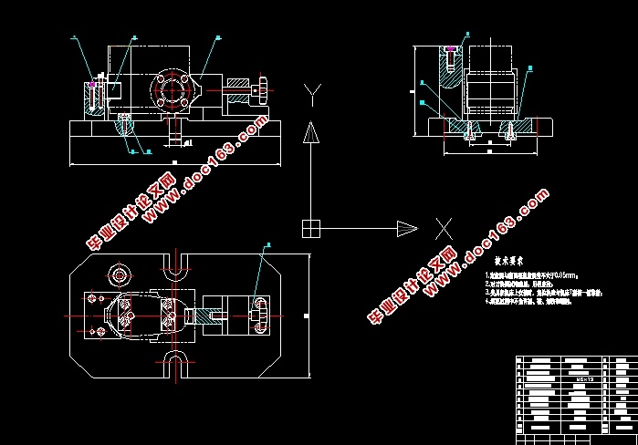
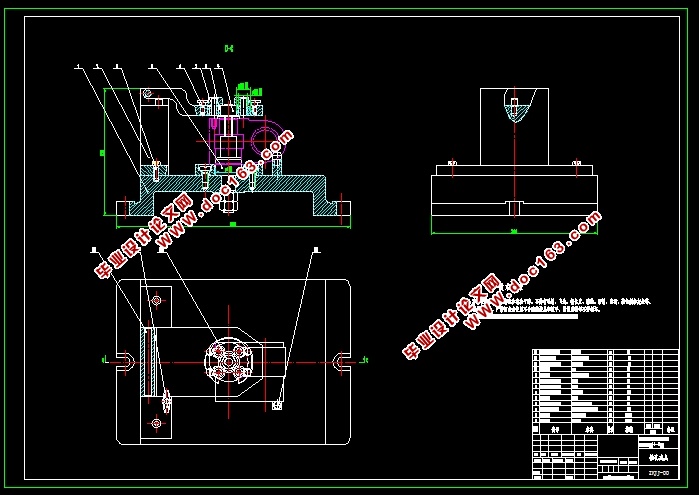
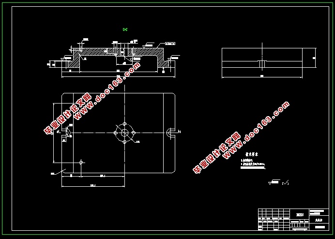
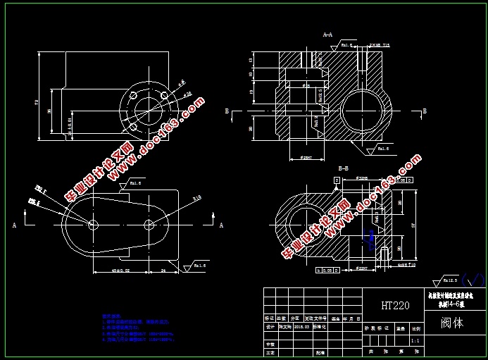
阀体的加工工艺编制及夹具设计(含CAD图,CAXA图纸,工艺卡)任务书,论文说明书15000字,CAD图纸4张,CAXA图纸4张,工艺卡,实习调研报告)
摘 要
本次设计选定的题目是阀体的加工工艺编制及专用夹具设计。阀体的定义是在流体系统中,用来控制流体的方向、压力、流量的装置。阀体的加工质量直接影响阀门的精度、寿命和性能。
阀体的加工工艺编制主要包括工艺性分析、毛坯选择、工艺路线编制及工序设计等。首先对零件进行分析,了解零件的结构工艺性,然后选择毛坯和定位基准,并设计出零件的工艺路线,其次对零件各个工序进行设计计算,确定各工序的工序尺寸、加工精度及切削用量参数等。
为设计此套夹具查阅相关资料以及参考文献,本文中涉及的知识面有夹具设计、零件安装,加工工艺分析、数值计算,刀性能,测量技术、CAD制图、公差配台及加工设备等多方面的知识。设计专用夹具,主要内容包括定位方案、夹紧方案等。在定位方案中,进行了结构设计及定位误差计算,在夹紧方案中,确定了夹紧力及夹紧元件的选择。
通过本设计,保证了阀体零件的加工质量,提高了生产效率,减轻了工人的劳动强度。
关键词: 阀体;专用夹具;加工工艺
Abstract
The design of the selected subject is the valve body processing technology and special fixture design. The valve body is defined as a device used to control the direction, pressure and flow of fluid in a fluid system. The machining quality of the valve body directly affects the accuracy, life and performance of the valve.
The machining process of valve body mainly includes process analysis, blank selection, process planning and process design. Firstly, the parts are analyzed to understand the structural process of the parts, then the blank and positioning datum are selected, and the process route of the parts is designed. Secondly, the design and calculation of each part of the parts are designed to determine the size of the process, the machining accuracy and the parameters of the cutting amount.
In order to design this fixture to refer to relevant information and references, the knowledge involved in this paper includes fixture design, part installation, processing technology analysis, numerical calculation, tool performance, measurement technology, CAD drawing, tolerance matching table and processing equipment. Design special fixture, the main contents include positioning scheme, clamping scheme and so on. In the positioning scheme, the structural design and positioning error calculation are carried out, and the clamping force and the selection of clamping elements are determined in the clamping scheme. [资料来源:THINK58.com]
Through the design, the machining quality of the valve body parts is ensured, the production efficiency is improved, and the labor intensity of workers is reduced.
Keywords: The valve body;Special fixture;Processing technology
3.1 零件的工艺分析及生产类型的确定
3.1.1 零件的作用
题目所给的零件阀体,主要作用是通过螺纹与其他零件连接,达到控制流体开关、方向、压力及流量。
3.1.2零件的加工工艺
阀体是一个很重要的零件,因为其零件尺寸比较小,结构形状较复杂,其加工内孔的精度要求较高,此外还有上下端面,孔端面需要加工,对精度要去也很高。其内孔对孔端面有垂直度要求,因为其尺寸精度,几何形状精度和相互位置精度以及表面质量均影响阀是否能够良好的密封,进而影响其使用性能。
3.1.3零件的生产类型
本设计要求5000件所以生产类型是大批大量。
3.2选择毛坯种类绘制毛坯图
3.2.1确定毛坯种类
由零件图可知零件材料为HT220,生产批量为大批大量,零件结构一般复杂,所以选择金属型浇铸,因为生产率很高,所以可以免去多次造型,工件尺寸较小,单边余量不大,需要结构细密,能承受较大的压力,所以选择铸件做毛坯。 [资料来源:http://think58.com]
3.2.2确定毛坯尺寸及加工总余量
选择的毛坯铸造方法是金属模机器造型,零件的最大尺寸小于250mm,铸件的机械加工余量等级则为5-7级查文献[1]表2-11,选择6级。查文献[1]表2.2-4中查得高72mm的加工余量为2mm,即该毛坯尺寸为76mm;全长为57mm的加工余量为2mm,即该毛坯的尺寸为61mm,φ28H7加工余量为2 mm,即该毛坯的尺寸为φ26,φ22H8加工余量为2 mm,即该毛坯的尺寸为φ20。


[来源:http://think58.com]
目 录
摘 要 I
Abstract II
第1章 绪论 1
1.1 阀体的作用及发展情况 1
1.1.1 阀体的作用 1
1.1.2 阀体的发展情况 1
1.2 阀体加工阶段存在的问题 2
1.3 设计课题要达到的设计目的 3
第2章 阀体方案可行性论证 5
2.1 阀体加工工艺方案确定 5
2.2 方案论证 8
2.3 铣上端面A夹具设计 9
2.4 钻M6螺纹孔 9
第3章 工艺规程设计计算 10
3.1 零件的工艺分析及生产类型的确定 10
3.1.1 零件的作用 10
3.1.2 零件的加工工艺 10
3.1.3 零件的生产类型 10
3.2选择毛坯种类绘制毛坯图 10
3.2.1 确定毛坯种类 10
3.2.2 确定毛坯尺寸及加工总余量 11
3.2.3 毛坯图 11
3.3 各表面加工方法的选择 12
3.4 工序的机床设备、工艺装备 13
3.5 切削用量以及基本时间定额的确定 13
3.5.1 粗铣上端面 13
3.5.2 粗铣前端面 14
3.5.3 半精铣上端面 16
3.5.4 半精铣前端面 17
3.5.5 精铣上端面 18
3.5.6 精铣前端面 19
3.5.7 粗镗φ28H7的孔 20
3.5.8 粗镗φ35的孔 21
3.5.9 半精镗φ28H7的孔 22
3.5.10 粗镗φ22H7的孔 23
3.5.11 粗镗φ32H8的孔 24
3.5.12 粗镗φ36H8的孔 25
3.5.13 半精镗φ22H7的孔 25
3.5.14 钻M8的螺纹孔 26
[资料来源:THINK58.com]
3.5.15 钻M6的螺纹孔 27
3.6 铣平面夹具设计计算 29
3.6.1 问题的提出 29
3.6.2 确定定位方案,选择定位元件 29
3.6.3 定位误差分析 29
3.6.4 切削力及夹紧分析计算 30
3.6.5 确定夹紧机构 30
3.7 钻M6螺纹孔夹具设计计算 31
3.7.1 问题的提出 31
3.7.2 确定定位方案,选择定位元件 31
3.7.3 定位误差分析 31
3.7.4 导向装置的确定 32
3.7.5 切削力及夹紧分析计算 32
3.7.6 确定夹紧机构 33
3.8 环境保护和可持续发展方面的思考 33
第4章 产品的使用与维护 35
4.1 夹具的使用 35
4.2 夹具的维护 35
第5章 本科毕业设计特色专题 36
5.1 CATIA软件的介绍 36
5.2 铣平面夹具装配图三维设计 36
结 论 39
参考文献 40
致 谢 42 [来源:http://think58.com]
上一篇:阀体的加工工艺编制及专用夹具设计(含CAD图,CAXA图纸,工艺卡)
下一篇:柴油机壳体加工工艺及Φ66镗孔夹具设计(含CAD图,工序卡)
