法兰盘加工工艺及专用夹具设计(含CAD零件装配图爆炸图,工艺卡)

1.无需注册登录,支付后按照提示操作即可获取该资料.
2.资料以网页介绍的为准,下载后不会有水印.资料仅供学习参考之用.
密 惠 保
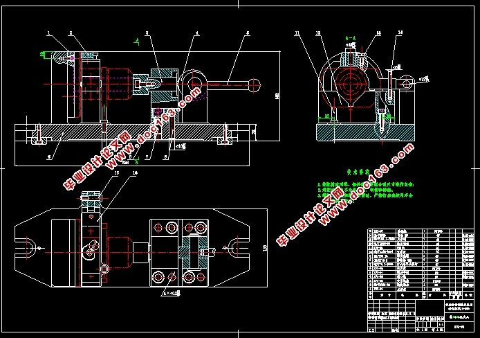
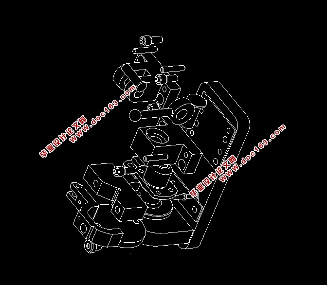
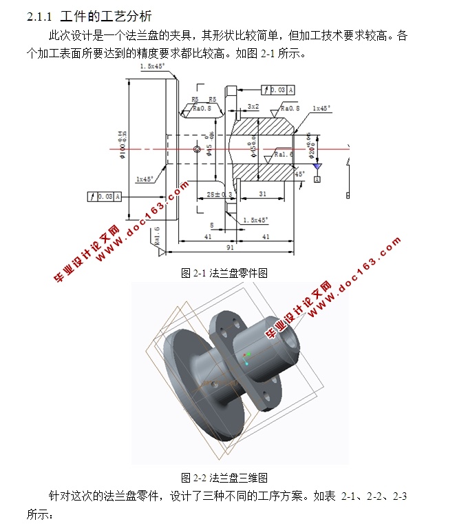
法兰盘加工工艺及专用夹具设计(含CAD零件装配图爆炸图,工艺卡)(任务书,论文说明书18000字,CAD图纸9张,工艺卡,实习调研报告)
摘 要
本次设计的目的是对车床法兰盘进行加工工艺的编制并对其中的部分工序进行专用夹具设计,编制的工艺方案需要符合经济性原则以及做到节能减排。设计的工艺方案和专用夹具要能够完成零件要达到的工艺要求。本次工艺方案设计过程中使用对比论证的方法在完成设计。设计完成了一套包括机床选择使用以及对应刀具选用在内的完整加工工艺方案,一套钻床专用夹具,一套铣床夹具的设计并且对其中一套专用夹具中包括夹具体在内的各种非标准件的三维实体图形绘制及三维实体装配。设计完成了两套专用夹具的二维A0装配图和一张夹具体的零件二维图。在设计完成之后,设计的加工工艺方案能够达到零件图纸所要求的工艺标准,加工出合格可用的零件,设计出的两套专用夹具可以达到使用要求。
关键词:工艺方案;法兰盘;三维实体装配;工艺标准
Abstract
The purpose of this design is carried out on the lathe flange machining process of special fixture design and the part of the process, the establishment of processing plan need to conform to the principle of economy, and achieve energy conservation and emissions reduction. The design process plan and special fixture should be able to meet the technical requirements of the parts. This process plan design process USES the method of comparative demonstration to complete the design. Designed a set of including machine tool use, as well as corresponding cutting tool selection, the complete machining process, a set of special fixture drilling machine, a set of milling fixture design and one set of special fixture, including clamp concrete in all kinds of standard parts of the three-dimensional entity graph drawing and assembly 3 d entity. The 2d A0 assembly drawing of two sets of special fixtures and a 2d assembly drawing of the specific parts of the clamps are designed. After the completion of a design, the processing technology of the design scheme can reach the standard drawings required by the process, the processing of qualified parts are available, and designed two sets of special fixture can meet the use requirements. [资料来源:http://www.THINK58.com]
Key words: process plan; Flange; Three-dimensional solid assembly; Technology standard


[资料来源:http://www.THINK58.com]
目 录
摘 要 I
第1章 绪 论 1
1.1 简述机械加工与工艺 1
1.2 简述机械加工工艺流程 1
1.3 描述夹具 2
1.4 机床夹具的基本功能 2
1.4.1 机床夹具的主要功能 3
1.4.2 机床夹具的特殊功能 3
1.5 未来机床夹具的主要发展方向 3
1.5.1 机床夹具的现阶段状况 3
1.5.2 现代机床夹具的发展方向 4
第2章 可行性分析 5
2.1 方案设计 5
2.1.1 工件的工艺分析 5
2.2 可行性论证评价 8
2.2.1 方案一可行性论证评价 8
2.2.2 方案二可行性论证评价 8
2.2.3 方案三可行性论证评价 8
2.2.4 方案确定 8 [资料来源:THINK58.com]
2.3 专用夹具设计 8
2.3.1 对工序8进行专用夹具设计 8
2.3.2 对工序9进行专用夹具设计 8
第3章 工艺规程设计计算 9
3.1 零件的作用 9
3.1.1 零件的工艺分析 9
3.1.2 确定毛坯的制造形式 9
3.2 加工粗,精基准的选择 11
3.2.1 选择粗基准 11
3.2.2 选择精基准 12
3.3 制定加工工艺路线 12
3.4 工时计算 13
3.4.1 工序 1 13
3.4.2 工序2 16
3.4.3 工序3 20
3.4.4 工序4 22
3.4.5 工序5 23
3.4.6 工序6 25
3.4.7 工序7 27
3.4.8 工序8 28
3.4.9 工序9 30 [来源:http://www.think58.com]
3.4.10 工序10 33
3.4.11 工序11 34
3.4.12 工序12 35
3.4.13 工序13 35
3.4.14 工序14 35
3.4.15 工序15 35
3.4.16 工序16 35
3.5 专用夹具设计 37
3.5.1 钻Φ4mmΦ6mm专用夹具设计 37
3.5.2 铣Φ90mm两端平面专用夹具设计 38
3.6 环境保护和可持续发展方面的思考 40
3.6.1 设计对环境的影响 40
3.6.2 设计与可持续发展 41
第4章 产品使用与维护 42
4.1 产品的使用方法 42
4.1.1 钻床夹具的使用方法 42
4.1.2 铣床夹具的使用方法 43
4.2 产品的维护 45
第5章 毕业设计特色专题 46 [资料来源:THINK58.com]
5.1 建模方法 46
5.2 零件建模 46
5.2.1 夹具体建模 46
5.2.2 V形块建模 46
5.2.3 偏心轮建模 47
5.2.4 后座块建模 47
5.2.5 钻模块建模 47
5.3 装配仿真 48
结 论 49
参考文献 50
致 谢 51
[资料来源:http://think58.com]
上一篇:差速器壳体加工工艺编制及专用夹具设计(含CAD图,CATIA三维,工艺卡)
下一篇:阀体的加工工艺编制及专用夹具设计(含CAD图,CAXA图纸,工艺卡)
