差速器壳体加工工艺编制及专用夹具设计(含CAD图,CATIA三维,工艺卡)

1.无需注册登录,支付后按照提示操作即可获取该资料.
2.资料以网页介绍的为准,下载后不会有水印.资料仅供学习参考之用.
密 惠 保
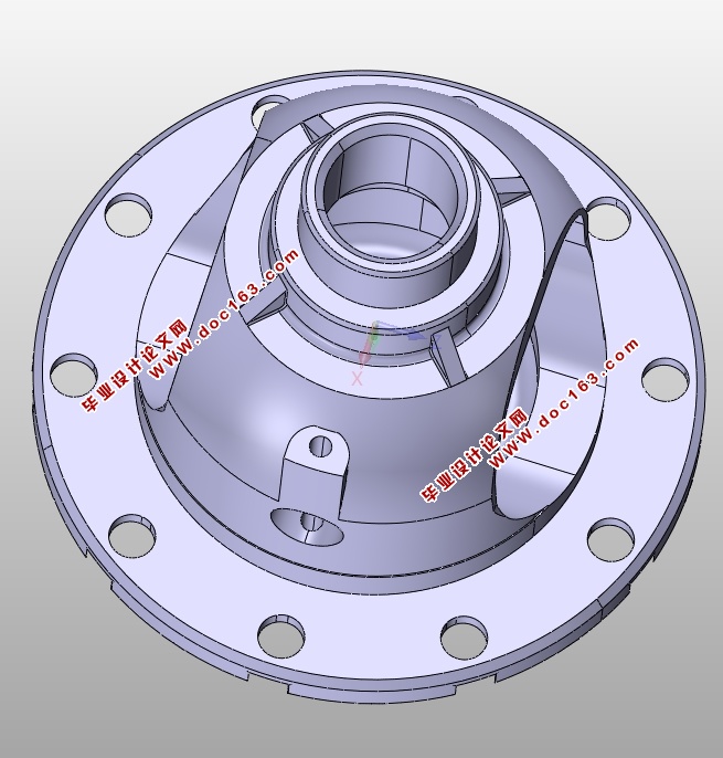
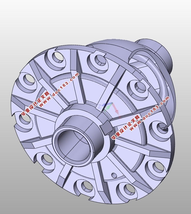
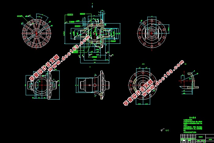
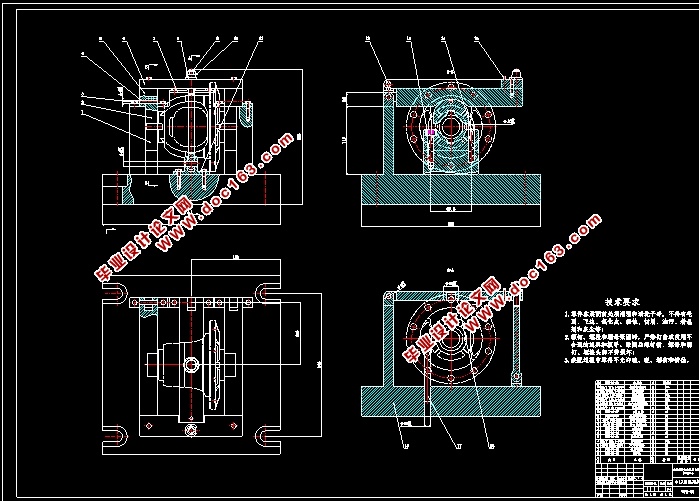
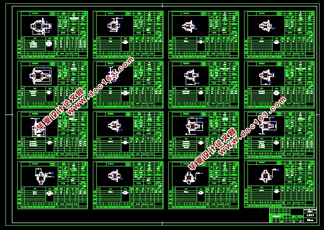
差速器壳体加工工艺编制及专用夹具设计(含CAD图,CATIA三维,工艺卡)(任务书,论文说明书18000字,CAD图2张,CATIA三维图,工艺卡,工序卡,实习调研报告)
摘 要
汽车差速器是能够使左、右(或前、后)驱动轮实现以不同转速转动的机构,功用是当汽车转弯行驶或在不平路面上行驶时,使左右车轮以不同转速滚动,即保证两侧驱动车轮作纯滚动运动。差速器壳体的形状是根据不同车型及差速器的结构确定的,作用是组合和支撑。本次工艺方案设计过程中使用对比论证的方法在完成设计。设计完成了一套包括机床选择使用以及对应刀具选用在内的完整加工工艺方案,两套钻床专用夹具的设计和其中一套专用夹具中包括夹具体在内的各种非标准件的三维实体图形绘制及三维实体装配。设计完成了两套专用夹具的二维A0装配图和一张夹具体的零件二维图。在设计完成之后,设计的加工工艺方案能够达到零件图纸所要求的工艺标准,加工出合格可用的零件,设计出的两套专用夹具也可以达到使用要求。
关键词:差速器壳体;加工工艺;专用夹具
Abstract
Automobile differential is to be able to make the right and left (or) before and after driving wheels at different speed of rotation mechanism, function is when the car turning driving or when driving on rough road surface, the left and right wheels at different speed rolling, guarantee on both sides of the drive wheels are pure rolling motion. The shape of differential housing is determined according to the structure of different types of cars and differential boxes.The designed process plan and special fixtures must be able to complete the process requirements for the parts to be achieved. The design of the process plan using the comparative demonstration method is completed.The design completes a complete processing scheme including the selection of the machine tool and the selection of the corresponding tool. The design of the two sets of special jigs for drill presses and the special fixtures include three-dimensional solid graphics of various non-standard parts including the clamps drawing and 3D solid assembly.A two-dimensional A0 assembly drawing of two special fixtures and a two-dimensional drawing of a specific part of the fixture were designed. After the design is completed, the designed machining process plan can meet the required process standards for parts drawings, and the qualified and usable parts can be machined. The two special fixtures designed can also meet the requirements for use.
[资料来源:http://think58.com]
Key words:differential case;the processing technology;specific fixt
3.1 零件的工艺分析及生产类型的确定
3.1.1 零件的作用
汽车差速器能够使左右(或前后)驱动轮实现以不同转速转动的机构,主要由左右半轴齿轮,两个行星齿轮及齿轮架组成。功用是当汽车转弯行驶在不平路面上时,使左右车轮以不同转速滚动,即保证两侧车轮作纯滚动运动。
差速器壳体在整个差速器组成中的功用是保证其他各个部件占据正确合理的位置,使之有一个协调运动的基础构件。差速器壳体零件质量的优劣将直接影响到轴和齿轮等零件的相互位置准确性及差速器组成后使用的灵活性与寿命[4]。
3.1.2 零件的加工工艺
具体加工工艺方案见第2章工艺路线一。
3.2 选择毛坯种类,绘制毛坯图
3.2.1 确定毛坯类型
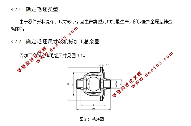
由于零件形状复杂,尺寸较小,且生产类型为中批量生产,所以选择金属型铸造毛坯[5]。
[资料来源:http://www.THINK58.com]

 [资料来源:http://think58.com]

[来源:http://think58.com]
目 录
摘 要 Ⅰ
Abstract Ⅱ
第1章 绪论 1
1.1 差速器作用及发展 1
1.1.1 差速器的作用 1
1.1.2 差速器的发展 1
1.2 差速器壳体的作用 1
1.3 加工工艺编制的发展 2
1.3.1 国际发展现状 2
1.3.2 国内发展现状 2
1.4 专用夹具作用及发展 2
1.4.1 专用夹具的作用 2
1.4.2 专用夹具的发展 3
1.5 设计目的 3
第2章 民意车差速器壳体加工工艺编制及专用设计计算方案设计及可行性论证 4
2.1 民意车差速器壳体工艺方案编制及专用夹具设计方案设计 4
2.1.1 方案一 4
2.1.2 方案二 5
2.1.3 方案三 5 [资料来源:http://www.THINK58.com]
2.2 方案可行性论证 6
2.2.1 方案一评价 6
2.2.2 方案二评价 6
2.2.3 方案三评价 7
2.2.4 方案确定 7
2.3 专用夹具设计 7
2.3.1 对工序080进行专用夹具设计 7
2.3.2 对工序090进行专用夹具设计 7
第3章 民意车差速器壳体加工工艺编制及专用设计计算 9
3.1 零件的工艺分析及生产类型的确定 9
3.1.1 零件的作用 9
3.1.2 零件的加工工艺 9
3.2 选择毛坯种类,绘制毛坯图 9
3.2.1 确定毛坯类型 9
3.2.2 确定毛坯尺寸及机械加工总余量 9
3.2.3 各表面加工方法的选择 10
3.3 工序的机床设备 11
3.4 机械加工余量及工序尺寸 12 [来源:http://www.think58.com]
3.5 工序设计 13
3.5.1 工序040设计 13
3.5.2 工序050设计 17
3.5.3 工序060设计 20
3.5.4 工序070设计 22
3.5.5 工序080设计 24
3.5.6 工序090设计 25
3.5.7 工序100设计 28
3.5.8 工序110设计 29
3.5.9 工序120设计 30
3.5.10 工序130设计 30
3.5.11 工序140设计 32
3.5.12 工序150设计 36
3.5.13 工序160设计 37
3.5.14 工序170设计 37
3.5.15 工序180设计 39
3.5.16 工序190设计 43
3.5.17 工序200设计 44
3.5.18 工序210设计 44
3.5.19 工序220设计 45
3.6 专用夹具设计 46
3.6.1 钻φ17mm底孔专用夹具 46
3.6.2 钻φ5mm孔专用夹具 48
3.7 环境保护和可持续发展方面的思考 50
3.7.1 设计对环境的影响 50
3.7.2 设计与可持续发展 51
第4章 产品使用与维护 52
4.1 产品的使用方法 52
4.2 产品的维护 52
第5章 毕业设计特色专题 53
5.1 软件简介 53
5.2 三维实体设计 53
5.2.1 操作步骤 53
5.2.2 实物图形 57
5.2.3 三维实体装配图 59
结 论 60
参考文献 61
致谢 63
[版权所有:http://think58.com]
上一篇:三拐曲轴加工工艺及专用夹具设计(含CAD零件装配图,CREO三维图,工序卡)
下一篇:法兰盘加工工艺及专用夹具设计(含CAD零件装配图爆炸图,工艺卡)
