小型涡轮的夹具设计(含CAD零件图夹具装配图)

1.无需注册登录,支付后按照提示操作即可获取该资料.
2.资料以网页介绍的为准,下载后不会有水印.资料仅供学习参考之用.
密 惠 保
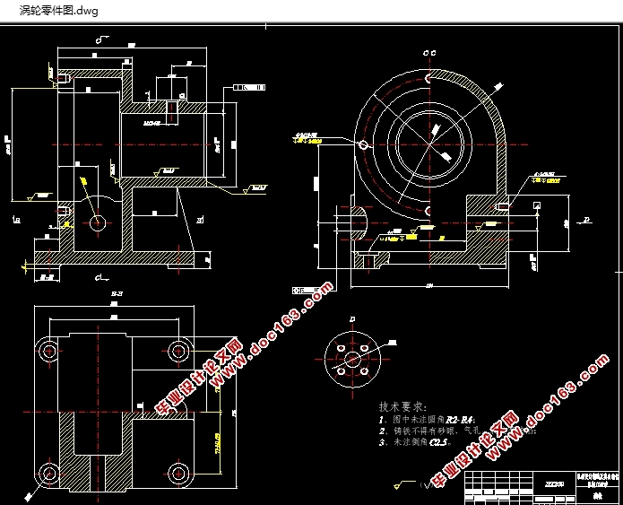
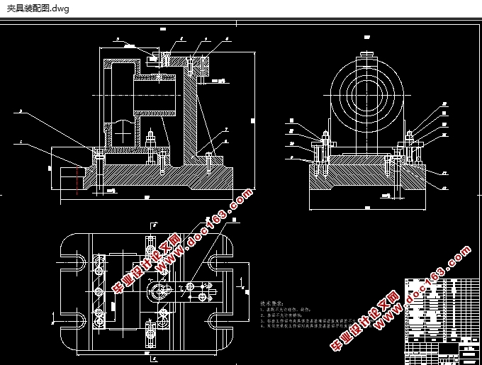
小型涡轮的夹具设计(含CAD零件图夹具装配图)(任务书,论文说明书11000字,文献综述,CAD图纸4张)
摘 要
本次毕业设计的主要内容是小型涡轮的夹具设计。我将机械制造技术基础和其它课程的基本理论和方法结合起来,为了能够完成小型涡轮的夹具的设计任务,首先应该归纳发挥所学的知识,选取正确的设计方法。首先确立了涡轮的机械加工工艺过程。确立了正确的工艺设计内容,接下来应用正确的工艺计算方法,对具体工艺内容进行了合理的分析、设计、计算。本文主要涉及到工艺参数、切削力、切削功率、切削速度、定位误差、夹紧力。确立了对涡轮的加工工艺路线,以底面作为基准符合该零件的加工要求,该加工工艺方案满足粗基准选择的基本要,并且满足精基准选择的四项原则。本夹具为使用钻床加工的专用夹具,钻床专用夹具的特点是针对性强、布局紧凑、操纵简单、生产率高。在小型涡轮的夹具设计的具体设计中,夹具的设计满足小型涡轮的夹具设计的总体方案,保证零件加工的精度等基本要求,具有较高的生产效能和低的制造成本,具有优秀的构造工艺性。
关键词: 加工工艺; 专用夹具; 涡轮
Abstract
This graduation design main content is small turbine jig design. I will combine the basic theory and method of foundation of mechanical manufacturing technology and other courses, in order to be able to complete the design of small sized turbine fixture, first of all should induction play learned knowledge, the selection of the correct design method.Firstly, the machining process of the turbine is established.. The correct technological design content is established, and the correct technology calculation method is applied, and the reasonable analysis, design and calculation of the concrete technology are carried out.. This paper mainly involves the process parameters, cutting force, cutting power, cutting speed, positioning error and clamping force.. Established on the turbine machining line, to the bottom surface as a benchmark in line with the parts of the processing requirements, the processing program meet the benchmark crude selection of basic, and meet a fine selection of basis of the four principles. This jig for the use of special fixture, drilling machine tool, special fixture is targeted, compact layout, simple operation, high productivity. In the specific design of the small turbine of fixture design, fixture design meet the overall scheme of the fixture design of small turbine and ensure machining precision of the basic requirements and has high production efficiency and low manufacturing cost, has excellent structure of the process. [资料来源:www.THINK58.com]
Key words: Process technology; Special fixture; Turbine
3.1 明确设计任务
本次专用夹具设计任务是:用钻床钻M12-6H螺纹底孔,孔口倒角2×45°和攻螺纹M12-6H的专用夹具。
3.2 确定定位方案
由工序卡可知,螺纹孔没有位置要求,在本夹具设计中,限制该零件的六个自由度。用“一面两孔”组合定位方法的具体定位。由零件图已知,M12-6H孔不垂直度要求和平行度要求,选择箱体表面的定位基准平面的底部,两侧面和定位块定位辅助,所以三自由度是有限制的。再用底面的两个对角孔进行定位,为避免重复定位,其中一个用削边销,另一个用定位销。如此六个自由度全被制约,工件被彻底定位。为了便于加工,采选可换钻套。本工序基本定位面选择底面,运用了箱体加工中“一面两孔”的定位方法,定位精度较高。
3.3 设计夹紧机构
根据生产要求,手动夹紧方式便可以满足要求。再使用快速螺旋夹紧机构进行夹紧,可以方便夹紧。夹具的夹紧力可以防止工件的翻转和振动钻削力的作用下避免影响工件质量。
[资料来源:THINK58.com]


目 录
第1章 引 言 1 [来源:http://think58.com]
1.1 涡轮综述 1
1.2 机械制造技术的地位与发展 1
1.3 涡轮夹具的发展概况 2
1.4 设计说明书简述 3
第2章 涡轮机械加工的总体设计 4
2.1 涡轮工艺分析 4
2.1.1 涡轮作用 4
2.1.2 涡轮工艺分析 4
2.2 选择毛坯 5
2.3 确定铸件机械加工余量、毛坯尺寸和公差 5
2.4 设计毛坯图 6
2.4.1 确定圆角半径 6
2.4.2 确定毛坯的热处理方式 6
2.5 机械加工工艺路线的制订 7
2.5.1 选择定位基准 7
2.5.2 制订工艺路线 8
2.5.3 分析加工工艺过程 10
2.5.4 选择加工设备 11
2.5.5 确定工序尺寸 11
2.5.6 确定工序使用机床 12
第3章 夹具的设计 16
3.1 明确设计任务 16
3.2 确定定位方案 16
3.3 设计夹紧机构 16
3.4 计算切削力和夹紧力 16
3.5 分析与计算定位误差 17
3.5.1 确定定位元件尺寸及公差 17
3.5.2 计算定位误差 17
3.6 设计夹具体 18
3.7 选择夹具与机床连接元件 18
3.8 夹具的使用说明 18 [资料来源:www.THINK58.com]
3.9 夹具的结构特点 18
结论 19
参考文献 20
致谢 21
[来源:http://think58.com]
上一篇:柴油机气缸体顶底面粗铣组合机床总体及夹具设计(含CAD图)
下一篇:柴油机气缸盖加工工艺及夹具设计(含CAD零件图夹具装配图)
