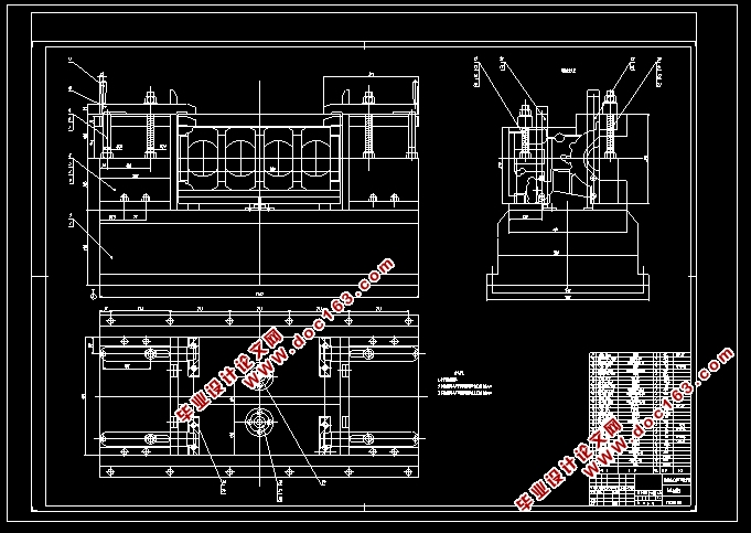
柴油机气缸体顶底面粗铣组合机床总体及夹具设计(含CAD图)

1.无需注册登录,支付后按照提示操作即可获取该资料.
2.资料以网页介绍的为准,下载后不会有水印.资料仅供学习参考之用.
密 惠 保
柴油机气缸体顶底面粗铣组合机床总体及夹具设计(含CAD图)(任务书,论文说明书10000字,文献综述,CAD图纸4张)
摘要
本论文设计的主题是柴油机气缸体顶底面粗铣组合机床总体及夹具设计。根据缸体的大小、形状、材料、加工部分的结构和加工精度,表面粗糙程度的一系列要求,实现工件快进和方便移动工作台;加工飞机是一架飞机,所以刀具硬质合金端铣刀的选择。夹具安装在移动工作台。在加工零件的定位,这个程序使用了“一面两销”定位,方便达到最理想的效果。夹紧是通过手动夹紧,以四个压板实现夹紧,这样能很好的防止夹紧力作用下工件产生形变。因为被加工的零件体积、重量较大,所以采用支承板支承。同时通过夹具设计误差分析,可以更好地保证加工精度。
通过设计满足加工要求,为了完成柴油机的粗加工。
关键词: 组合机床; 夹具; 缸体; 铣削
Abstract
Roughing the surface and the bottom of the cylinder block of the diesel engine combined machine and fixture overall diesel。
My design subject is diesel engine combination machine tools and fixture design as a whole. According to the cylinder block size, shape, material, processing parts of the structure and machining accuracy, surface roughness and a series of requirements, in order to realize workpiece fast forward into the convenient to moving workbench and workers; By processing plane is large plane, so the cutting tool choice carbide end milling cutter. Clamp installed on the top of the sliding table. In the aspect of the positioning of the processed parts, this scheme adopts the "side two pin" way of positioning, convenient to achieve the ideal effect. Clamping is by manual clamping to four clamp clamping, this can be a very good prevent clamping force is generated under the action of deformation. Because of the processed parts volume, the weight is bigger, so the supporting plate bearing. At the same time through the error analysis of the fixture design, can better guarantee the machining precision.
[资料来源:THINK58.com]
Through the design satisfies the requirement of processing, in order to complete the rough machining of diesel engine.
Keywords: modular machine tool; fixture; cylinder block; milling
2.1被加工零件分析
被加工零件:柴油机气缸体
材料:HT250
硬度:HB180-240
年产量:65000件
加工部位:顶底面
处理要求:表面粗糙度的缸体加工精确至6.3,和顶部底部表面的大小需要精确到427 + 0.3毫米。
2.2机床结构的确定
根据具体要求,处理部分:顶底面粗铣,铣机床的选择。
对被加工零件的两侧移动工作台,分别设置两个铣刀,双电机驱动。
还应该包括两侧基,中间基,两铣头,两主轴箱和夹具。
2.3 本组合机床的特点
A.整体结构牢固,B.部分的刚性好,C.能调整尺寸范围较大,D.单元的工作来实现高效率的基础,即精度好,容易操作,E. 可以对铸件进行大行程走刀,F.强力铣削。
2.4 切削用量的确定
综合机床的过程中,整个测定过程中,过程方法和关键过程的切削用量更重要。切削用量的选择是否合理,加工精度、生产率、刀具耐用性、结构和机床的可靠性可以大大影响。 [资料来源:THINK58.com]
[来源:http://www.think58.com]


目 录
第一章 前言 1
第二章 机床的总设计 3
2.1被加工零件分析 3
2.2机床结构的确定 3
2.3 本组合机床的特点 3
2.4 切削用量的确定 4
2.4.1切削用量选择的特点 4
2.4.2切削用量选择的方法 4
2.4.3刀具的选择 4
2.4.4铣削用量的确定 4
2.4.5计算切削功率 5 [资料来源:http://www.THINK58.com]
2.5 各部件的选型 5
2.5.1选择电动机 5
2.5.2选择铣削头 6
2.5.3选择工作台 7
2.5.4选择侧底座 7
2.5.5选择中间底座 8
2.5.6机床分组 8
第三章 夹具的设计 9
3.1概述 9
3.1.1夹具 9
3.1.2机床的分类 10
3.1.3机床夹具的组成 10
3.1.4夹具设计方法与步骤 10
3.2设计准备 11
3.3定位装置的确定 11
3.3.1概述 11
3.3.2定位方式 12
3.3.3定位元素 12
3.4确定夹紧方案 14
3.4.1设计夹紧装置的要求 14
3.4.2夹紧力的确定 15
3.5 其它元件的设计 17
3.6夹具的公差配合与技术要求 17
3.6.1制定夹具公差与技术要求的基本原则 17 [资料来源:http://THINK58.com]
3.6.2夹具公差的制定 17
3.6.3夹具技术要求的制定 18
3.7工序的精度分析 19
3.7.1定位误差的分析与计算 19
3.7.2夹紧误差的分析与估算 20
3.7.3对刀和导向误差 21
3.7.4夹具的位置误差 22
3.7.5加工方法误差 22
3.7.6保证加工精度的条件 23
总 结 24
参 考 文 献 25 [资料来源:http://THINK58.com]
上一篇:过桥齿轮轴的工艺和工装设计(含CAD图,PROE三维图)
