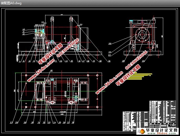
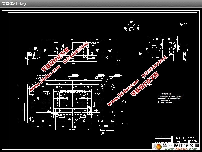
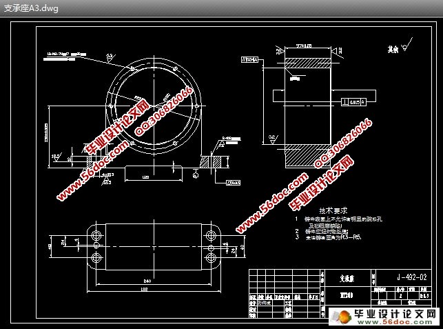
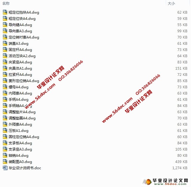
发动机曲轴箱镗半圆孔夹具设计(含CAD零件图装配图)

1.无需注册登录,支付后按照提示操作即可获取该资料.
2.资料以网页介绍的为准,下载后不会有水印.资料仅供学习参考之用.
密 惠 保
发动机曲轴箱镗半圆孔夹具设计(含CAD零件图装配图)(论文说明书13700字,CAD图25张)
摘 要:机床夹具是机械加工工艺系统的重要组成部分,为保证工件的某工序的加工要求,必须使工件在机床上相对刀具的切削或成形运动处于准确的相对位置。当用夹具装夹工件一批工件时,是通过夹具来实现这一要求的。本次设计是为镗曲轴箱主轴半圆孔而设计的专用卧式机床夹具。以工件一面两孔定位,以螺旋夹紧机构实现工件的夹紧,以回转式镗套实现刀具的导向。定位元件采用手柄伸缩式定位销一圆柱销、一菱形销及支承板。以手柄的转动控制定位销的上下运动而实现工件两孔的定位。夹紧装置采用螺母、压板、活动压块和拉紧杆。导向装置采用导向套、导向键等。
本文介绍了夹具的研究背景和发展趋势、课题的作用和意义、机床夹具的组成、镗床夹具的机构特点,以及492曲轴箱发动机镗半圆孔的夹具设计过程。
关键词:夹具;定位;夹紧;导向
492 Engine Crankcase Boring Semi-circular Fixture Design
Abstract:The tool fixture is an important component of the machine finishing craft system ,for guaranteeing the processing request of some working procedure of work piece , must make work piece move to cutting or taking shape of the cutter in the accurate relative position . When using a number of workpiece fixture workpiece clamping,Through the fixture to achieve this requirement . The project is on the horizontal special fixture for boring axis hemicycle of crankcase .Positioning by the workpiece side and two bores , clamping by spiral clamping mechanism , and set to achieve with rotary boring tool orientation. Positioning components take use of telescopic handle -a cylinder pin a diamond pin, and bearing plates . To achieve workpiece positioning of the two holes by controlling the up and down movement of the handle rotational pin. While clamping installations use nuts, platen, activities Press and taut rod, Oriented installations make use of guidance sets, and other key guidance.. [资料来源:http://think58.com]
This article introduced the jig research background and the trend of development, the topic function and the significance, the jig composition, Jig Boring Machine institutional characteristics, and 492 engine crankcase Boring hemicycle of the fixture design process.
Keyword : jig ;positioning;clamps; orientation


目 录
摘 要 1
[资料来源:www.THINK58.com]
关键词 1
1 前言 2
1.1 课题的背景及发展趋势 2
1.2课题的作用和意义 3
1.3机床夹具的分类与组成 3
1.4 镗床夹具的结构特点 5
2 总体方案的研究 8
2.1 产品零件加工部位的技术要求 8
2.2 总体结构及工作原理 9
3 夹具的总体设计 10
3.1 定位装置的设计 10
3.2 夹紧装置的设计 15
3.3 导向装置的设计 18
3.4 夹具体与其它装置的设计 21
3.5 夹具总图上的尺寸、公差 25
4 定位误差的分析和计算 26
4.1 定位误差的基本概念 26
4.2 定位误差的计算 26
5 结论 28
参考文献 29
致谢 30
[版权所有:http://think58.com]
上一篇:发动机曲轴箱工艺孔钻床夹具设计(含CAD零件图装配图)
下一篇:汽车连杆加工工艺及夹具设计(含CAD零件图装配图,工艺卡)
