气门摇臂轴支座零件的加工工艺规程设计

1.无需注册登录,支付后按照提示操作即可获取该资料.
2.资料以网页介绍的为准,下载后不会有水印.资料仅供学习参考之用.
密 惠 保
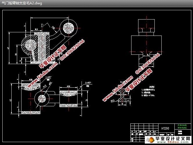
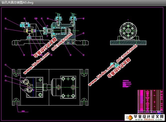
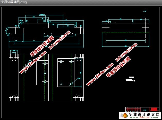
气门摇臂轴支座零件的加工工艺规程设计(论文说明书10900字,工序卡,工艺卡,CAD图纸3张)
摘要
本文设计了气门摇臂轴支座零件的加工工艺规程,该规程可以很好满足生产实践的指导;。文章首先介绍了气门摇臂轴支座的作用和工艺分析,其次确定毛坯尺寸,然后进行了工艺规程设计,最后进行夹具设计。此次设计是对气门摇臂轴支座的加工工艺和夹具设计,其零件为铸件,具有体积小,零件结构简单的特点,由于面比孔易加工,在制定工艺规程时,就先加工面,再以面为基准来加工其它,其中各工序夹具都采用专用夹具,其机构设计简单,方便且能满足要求。
关键词:机械加工工艺规程、专用夹具、定位误差、夹紧力
ABSTRACT
This paper introduces the design of valve lock shaft bearing parts processing procedure, this procedure can very well meet the production practice guidance This article introduces the role and process analysis of the valve rocker arm bearing support,followed by determining blank size, and then proceed to order the design process, the final fixture design. What will be disgned is The machining process and fixture design of the Valve Rocker Arm Bearing support,which has the chatacteristics of three abstrcat.its components for castings, with a small size, simple structure and the characteristics of parts,because the surface is easier than the easy processing, point of order in the development process, the surface on the first processing , and then to surface as a benchmark to other processing, including the processes used special fixture, and its design is simple, convenient and can meet the requirements. [资料来源:http://www.THINK58.com]
Keywords: mechanical processing procedure, special jig, positioning error, clamping force


目录
摘要 1
绪论 3
第 1 章. 零件的分析 4 [资料来源:http://THINK58.com]
1.1 零件的作用 4
1.2 零件的工艺分析 4
第2章 工艺规程设计 5
2.1确定毛坯 5
2.3工艺路线的拟定 7
2.4机床的选择 9
2.5夹具选择 9
2.6刀具选择 9
2.7 量具选择 10
2.8 工序尺寸确定 10
2.9 确定切削用量及基本工时 10
2.9.2 工序Ⅱ粗铣上端面 11
2.9.3 工序Ⅲ(粗铣 、 两圆柱两端面)切削用量及时间定额 12
第3章 夹具设计 18
3.1问题的提出 18
3.2夹具的设计 18
结论 27
致谢 28
参考文献 29 [资料来源:www.THINK58.com]
上一篇:S86A减速器壳体的工艺设计
下一篇:钻床用杠杆钻φ10孔专用夹具设计
