皮圈架座组合机床及专用夹具设计

1.无需注册登录,支付后按照提示操作即可获取该资料.
2.资料以网页介绍的为准,下载后不会有水印.资料仅供学习参考之用.
密 惠 保
皮圈架座组合机床及专用夹具设计(任务书,开题报告,外文翻译,进度计划表,论文说明书16000字,cad图纸2张)
摘 要
随着自动化应用的逐步提高,组合机床越来越多的出现在现代工厂中,组合机床是以通用部件为基础,配以工件特定外形和加工工艺设计的专用部件和夹具,组成的半自动或自动专用机床。它一般采用多轴,多刀,多过程,多方位多站同时处理方法,生产效率高,比一般机器几个几倍到几十倍。作为合作的通用部件已经标准化系列,可灵活配置,可缩短设计制造周期。因此,组合机床在大规模生产的低成本和高效率的优点相结合,已被广泛地使用,可用于形成自动生产线。
本次设计为皮圈架座钻孔专用机床,同时完成3个孔的加工。主要有以下几个方面:
(1)制定工艺方案。了解被加工零件的加工特点、精度和技术要求、定位夹紧情况以及生产率的要求等。确定在组合机床上完成的工艺内容及其加工方法。这里要确定加工工步数,决定刀具的种类和型式。
(2)机床结构方案的分析和确定。根据工艺方案确定机床的型式和总体布局。在选择机床配置型式时,既要考虑实现工艺方案,保证加工精度、技术要求及生产效率;又要考虑机床操作、维护、修理是否方便,排屑情况是否良好。
(3)组合机床总体设计。确定机床各个部件间的相互关系,选择通用部件和刀具的导向,计算切削用量及机床生产率。绘制机床的总联系尺寸图及加工示意图等。
关键词:组合机床;多轴箱;三图一卡;夹具设计
Abstract
With the gradual improvement of automation, machine tool more and more in modern factories, machine tool based on common components, together with the specific shape of the workpiece and process design special parts and fixtures, composed of semi-automatic or automatic dedicated machine. It is commonly used multi-axis, multi-tool, multi-process, multi-faceted or multi-station processing at the same time, the production efficiency several times or more higher than the general machine. Common components have been standardized for serialization, can be flexibly configured, you can shorten the design and manufacturing cycle. Therefore, the combination of machine combines the advantages of low cost and high efficiency has been widely used in mass production, and can be used to form an automatic production line.
[资料来源:www.THINK58.com]
The design for the apron mountings drill special machine tools, completed three hole machining. Mainly the following aspects:
(1) to develop a process plan. Learn about the processing characteristics of the machined parts, precision and technical requirements, the positioning clamping and productivity requirements. Determine the combination of machine tool technology content and its processing method. To determine the number of processing steps, determine the type of tool and type.
(2)Machine analysis of the structure of the program and OK. According to the technical program to determine the type and the overall layout of the machine. Machine configuration type is selected, it is necessary to consider the process scheme to ensure accuracy, technical requirements and production efficiency; will have to consider the operation of the machine, maintenance, repair, chip case is good.
(3) a combination of the overall machine design. Determine the relationship between the various components of the machine, select the common components and tool-oriented computing cutting and machine productivity. Draw machine total contact size figure and processing schematic diagram. [资料来源:http://www.THINK58.com]
Keywords: combination of machine tools; multi-axle; three card; fixture design
本课题研究的主要内容
1.制定工艺方案。了解被加工零件的加工特点、精度和技术要求、定位夹紧情况以及生产率的要求等。确定在组合机床上完成的工艺内容及其加工方法。这里要确定加工工步数,决定刀具的种类和型式。
2.机床结构方案的分析和确定。根据工艺方案确定机床的型式和总体布局。在机器配置类型的选择,有必要考虑实施过程中的计划,以确保准确性,技术要求和生产效率;又要考虑机床操作、维护、修理是否方便,排屑情况是否良好。
3.组合机床总体设计。确定某些机器的各个组件之间的相互作用,选择通用的组件和工具的定向力,计算切割用量,机器的生产率。绘制机床的总联系尺寸图及加工示意图等。
工件的分析
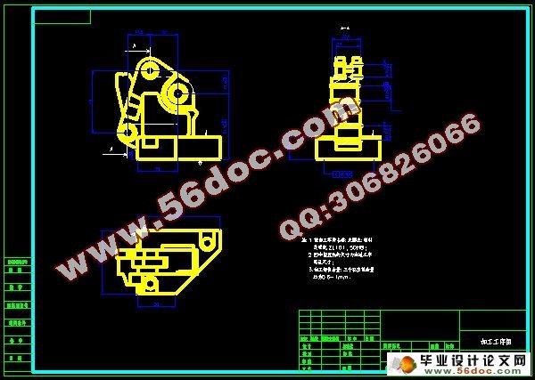
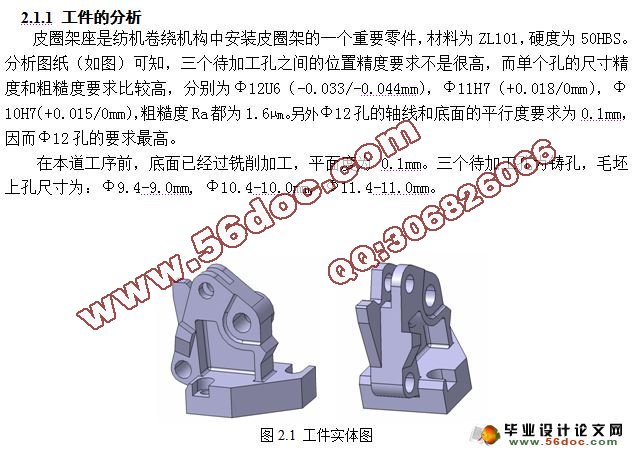
皮圈架座是纺机卷绕机构中安装皮圈架的一个重要零件,材料为ZL101,硬度为50HBS。分析图纸(如图)可知,三个待加工孔之间的位置精度要求不是很高,而单个孔的尺寸精度和粗糙度要求比较高,分别为Φ12U6(-0.033/-0.044mm),Φ11H7(+0.018/0mm),Φ10H7(+0.015/0mm),粗糙度Ra都为1.6µm。另外Φ12孔的轴线和底面的平行度要求为0.1mm,因而Φ12孔的要求最高。 [资料来源:http://think58.com]
在本道工序前,底面已经过铣削加工,平面度为0.1mm。三个待加工孔为铸孔,毛坯上孔尺寸为:Φ9.4-9.0mm, Φ10.4-10.0mm, Φ11.4-11.0mm。
[资料来源:http://think58.com]


目 录
摘 要 III
Abstract. IV
目 录 V [资料来源:www.THINK58.com]
1 绪论 1
1.1 课题来源和意义 1
1.2 课题背景 1
1.3 组合机床技术装备研究现状和发展趋势 1
1.4 本课题研究的主要内容 2
2 组合机床的总体设计 3
2.1 前期调查研究 3
2.1.1 工件的分析 3
2.1.2 现场工艺调查 3
2.2 组合机床方案的制定 4
2.2.1 制定工艺方案 4
2.2.2 确定组合机床的配置形式和结构方案 4
2.3 确定切削用量及选择刀具 5
2.3.1 确定工序间余量 5
2.3.2 选择切削用量 6
2.3.3 确定切削力、切削扭矩、切削功率 6
2.3.4 选择刀具结构 7
2.4 组合机床总设计“三图一卡”的编制 7
2.4.1 被加工零件工序图 8
2.4.2 加工示意图 9
2.4.3 机床联系尺寸图 11 [来源:http://think58.com]
2.4.4 生产率计算卡 13
3 多轴箱的设计 15
3.1 绘制多轴箱设计原始依据图 15
3.2 齿轮模数选择 16
3.3 多轴箱的传动设计 17
3.4 绘制传动系统图 18
3.5 传动零件的校核 20
4 夹具设计 24
4.1 机床夹具的概述 24
4.1.1 机床夹具的组成 24
4.1.2机床夹具的类型 24
4.2工件结构特点分析 24
4.3工件定位方案和定位元件的设计 24
4.4夹紧方案和夹紧元件的设计 24
4.5夹具的性能及优点 25
4.6夹具体的设计 25
4.7误差的分析与计算 25
4.8夹具精度分析计算 26
5 结论与展望 28
5.1结论 28
5.2不足之处及未来展望 28
致 谢 29 [资料来源:http://think58.com]
参考文献 30
[资料来源:http://THINK58.com]
下一篇:钳块加工工艺及专用夹具设计(CAD,SolidWorks三维)
