上下料桁架机器人电气控制系统设计

1.无需注册登录,支付后按照提示操作即可获取该资料.
2.资料以网页介绍的为准,下载后不会有水印.资料仅供学习参考之用.
密 惠 保
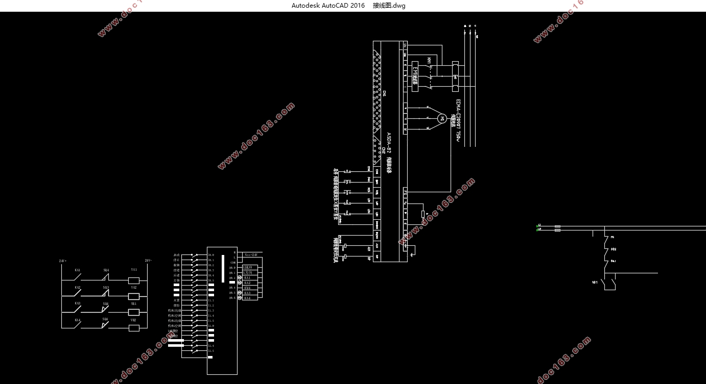
上下料桁架机器人电气控制系统设计(任务书,开题报告,论文说明书17000字,CAD接线图1张)
摘 要
随着现代科技的发展,桁架机械手在现代化生产流水线、物料搬运等方面有着越来越重要的价值,成为为企业减少人力成本增加劳动效率不可或缺的一环。目前桁架机械手的控制系统存在控制精度低,搬运效率不够高的问题,本文就PLC控制和触摸屏监控的相关理论,根据实际的桁架机械手动作要求,完成了对其运动控制回路的基本设计和软件模块的编程,对系统的整体构造,物理回路,控制方式以及控制流程等方面进行了讨论研究
本文先对实际的生产工况进行分析,根据桁架机械手需要完成的动作,对不同的控制方式进行比较,选定以电气控制为主气动控制为辅的整体控制方式,然后再由对抓取对象的分析通过需要的转速和扭矩比较了步进电机和伺服电机的性能之后,选取伺服电机作为主驱动模块控制机械手的移动,气压驱动回路作为副驱动模块控制手爪的抓取;最后通过对I/O点的统计和控制器的脉冲输出性能选择了西门子S7-200PLC作为主控制器,根据控制要求设计外部接线图并在此基础上完成对脉冲驱动伺服模块、手爪抓取模块、回原点和示教等模块的流程图规划和程序编写。
本文重点强调由脉冲控制伺服再由编码器反馈形成闭环位置控制的实现,包括对伺服电机的选型,PLC到伺服驱动器的接线及接口设计,选择方向加脉冲控制伺服电机的控制方式,实际运行需要的脉冲数和脉冲频率以及电子齿轮比等参数的计算,PLC对编码器反馈的差分信号的读取和对伺服驱动器参数设置等。并兼顾PLC对气压驱动方式中的中间继电器、电磁阀的控制回路设计。在此基础上论文完成了对桁架机械手控制系统的设计和编程。 [来源:http://www.think58.com]
关键词:伺服电机 PLC 上下料 控制系统
Design of Electric Control System for Loading and Unloading Truss Robots
Abstract
With the development of modern science and technology, truss manipulators have increasingly important values in modern production lines, material handling, etc., becoming an indispensable link for companies to reduce labor costs and increase labor efficiency. At present, the control system of truss manipulators has the problems of low control accuracy and low transfer efficiency. This paper presents the basic design and software modules of the motion control loop based on the relevant theories of PLC control and touch screen monitoring, according to the actual motion requirements of truss manipulators. The programming has discussed and studied the overall structure of the system, physical circuits, control methods, and control procedures.
This paper first analyzes the actual production conditions, compares the different control methods according to the actions that the truss manipulator needs to complete, and selects the overall control method that is supplemented by the main pneumatic control, and then the target After analyzing the performance of the stepper motor and the servo motor through the required speed and torque, the servo motor is selected as the main drive module to control the movement of the manipulator, and the air pressure drive circuit is used as the auxiliary drive module to control the grasping of the gripper; The statistics of the /O point and the pulse output performance of the controller selected the Siemens S7-200 PLC as the main controller. According to the control requirements, the external wiring diagram was designed and the pulsed servo module, gripper grab module, and origin return were completed. Flowchart planning and programming of modules such as teaching and teaching.
This article emphasizes the realization of the closed-loop position control by the pulse control servo and then feedback from the encoder, including the selection of the servo motor, the connection of the PLC to the servo driver and the interface design, the selection of the direction plus the pulse control servo motor control method, the actual operation The required number of pulses, pulse frequency, electronic gear ratio and other parameters are calculated. PLC reads differential signals fed back by the encoder and sets servo drive parameters. And take into account the PLC control of the intermediate relay, solenoid valve control circuit in the pneumatic drive mode. On this basis, the paper has completed the design and programming of the truss manipulator control system.
Key Words: servo motor PLC Loading and Unloading control systerm


目 录
摘 要 I
Abstract III
第一章 绪论 1
1.1 桁架机器人概述 1
1.2 工业机器人的发展史 2
1.3 桁架机器人的研究现状、应用和发展趋势 2
1.4 总结 3
第二章 总体设计部分 4 [资料来源:THINK58.com]
2.1设计目标分析 4
2.2桁架机器人的控制要求 5
2.3总体控制方案选择 6
2.3.1主轴驱动方式的选择 6
2.3.2 电机类型的确定 7
2.3.4 Z轴驱动方式的选择 7
2.4控制系统结构图 8
2.5经济性分析 9
第三章 具体电路硬件设计 11
3.1机械手的控制要求 11
3.2硬件选型 11
3.2.1 X向电机计算选型 11
3.2.2 Y向电机计算选型 12
3.2.3 PLC的选择 12
3.2.4 编码器的选择 13
3.2.5 触摸屏的选择 13
3.2.6模拟量输入/输出模块的选型 14
3.2.7 通信方式选择 14
3.3 I/O点的分配和统计 15
3.4 PLC以及伺服驱动器外部接线图 17
3.5高速脉冲输出方式 19
3.6伺服系统的电源接线图 19 [来源:http://think58.com]
3.7气压控制系统的设计 20
3.8闭环位置控制系统接口电路设计 22
3.8.1 差分信号处理电路 24
3.8.2 光电耦合处理电路 24
第四章 软件设计 26
4.1上电自检以及工艺流程图 26
4.2自动连续控制程序 28
4.3手动控制程序 29
4.4气动手爪控制程序 30
4.5回原点程序 31
4.6 伺服电机脉冲控制程序 33
4.7示教程序 34
4.8触摸屏设置 35
4.9设计主程序梯形图 37
4.10伺服驱动器参数设置 38
总结和展望 41
参考文献 42
附录 44
致 谢 49
下一篇:乘客电梯拖动系统的设计
