基于单片机的定时开关插座设计

1.无需注册登录,支付后按照提示操作即可获取该资料.
2.资料以网页介绍的为准,下载后不会有水印.资料仅供学习参考之用.
密 惠 保
基于单片机的定时开关插座设计(任务书,开题报告,论文9000字)
摘要
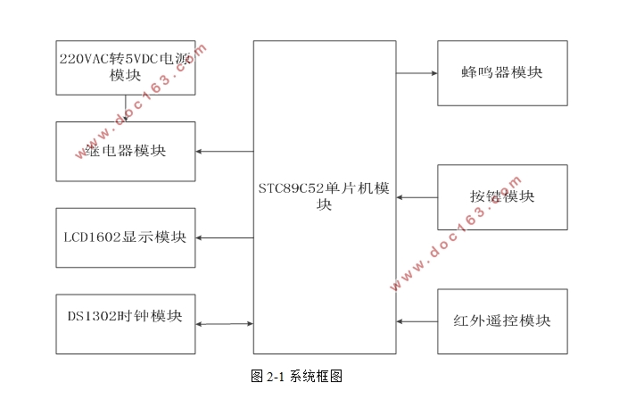
随着生活节奏的加快,生活水平的提高,节能、智能的观念深入人心,出于节能的目的设计出一款定时开关插座。本次毕业设计设计出一款定时开关插座,插座可通过按键或遥控器进行定时开关。本次设计由220VAC转5VDC电源模块,DS1302计时模块,STC89C52单片机模块,LCD1602显示模块,继电器模块,蜂鸣器模块,按键模块和红外遥控模块组成。本次设计使用STC89C52单片机作为驱动芯片,使用DS1302计时模块提供精确的计时,通过LCD1602显示模块显示年月日时分秒和操作界面,使用继电器控制插座电流的通断,并通过遥控器进行定时设置。本文包括硬件设计,软件流程的设计和电路的仿真与调试等部分,实现了定时插座的功能。最后分析了设计过程中出现的问题并对设计做出总结。
关键词:STC89C52单片机定时开关红外遥控
The Timer Socket Based on MCU
Abstract
The perception of energy conservation and intelligent goes deep into families, with the life increasing and improving quickly,And we design timer socket for energy conservation. The design is the timer socket,And the main function of timer socket is that we can time by key or IR Remote.The design consists of STC89C52,DS1302,LCD1602,220VAC to 5VDC power supply,buzzer,key and relay. The design’s driver microchip is STC89C52, The design uses the DS1302 to supply more accurate time,And the design uses LCD1602 to display the year,the month,the day,the hour,the minute,the second,and the operation interface.The design also uses the relay to control the on and off,And the timer socket can time by the remote control. In this paper, the design of the system was introduced through three aspects including the hardware modules, software flow pattern and circuit design and debugging. At the end of this paper, the problems happened during the process of designing the system was summarized. [来源:http://www.think58.com]
Keyword: STC89C52;the timer socket;IR Remote
[版权所有:http://think58.com]


目录
摘要 I
Abstract II
目录 III
第一章 绪论 1
1.1背景 1
1.2设计目标 1
1.3论文结构 2
第二章 硬件电路设计 3
2.1系统功能 3
2.2系统原理 3
2.3 硬件模块介绍 4
2.3.1 STC89C52单片机模块 4
2.3.2 220VAC转5VDC电源模块 5
2.3.3 DS1302时钟模块 8
2.3.4 LCD1602显示模块 9
2.3.5 继电器模块 9
2.3.6 蜂鸣器模块 10
2.3.7 按键模块 11
2.3.8 红外遥控模块 11
2.4 本章小结 12
第三章 程序设计 13
3.1 程序的总体设计 13
3.1.1 系统初始化 13
3.1.2 设置时间函数的设计 14
3.1.3 模式选择函数的设计 14
3.1.4 设置定时函数 15
3.1.5 中断函数的设计 15
3.1.6 红外遥控流程 16
3.1.7 DS1302函数的设计 17
3.1.8 LCD1602显示函数的设计 18
3.1.9 继电器执行流程 18
3.1.10 主程序的流程图 19
3.2 本章小结 19
第四章 系统测试与结果 21
4.1 测试与结果 21
4.1.1 软件仿真 21
4.1.2 硬件测试结果 24
4.2 调试过程中遇到的问题 26
4.3 本章小结 29
第五章 总结 30
参考文献 31
致谢 32
[资料来源:http://THINK58.com]
