
基于单片机的防酒驾模拟系统设计
1.无需注册登录,支付后按照提示操作即可获取该资料.
2.资料以网页介绍的为准,下载后不会有水印.资料仅供学习参考之用.
密 惠 保
基于单片机的防酒驾模拟系统设计(论文11000字)
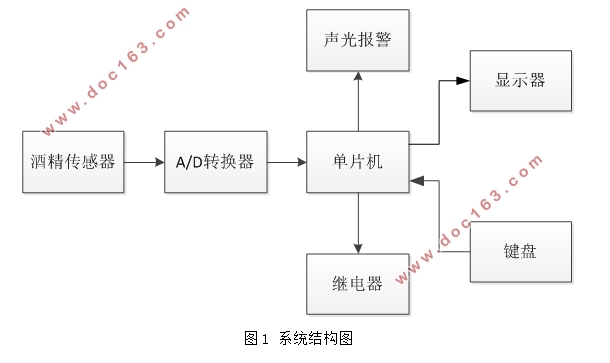
摘 要:模拟一款基于单片机的防酒驾系统,连接酒精传感器、数模转换器、灯光语音报警器、继电器、显示屏等硬件设备。酒精传感器检测到空气中的酒精浓度后,通过数模转换器将传感器所检测到的模拟信号转换为数字信号,并将空气中的酒精浓度值显示在液晶显示屏上。单片机会对浓度进行判断,超过设定标准则发出声光报警,并且能同汽车引擎系统衔接,断开发动机,使酒驾人员无法启动汽车。通过软硬件的设计和调试,成功制作了该模拟系统。在10~1000ppm的酒精浓度范围中,可以准确地检测出酒精浓度,并且做出相应的报警措施。
关键字:单片机,防酒驾,酒精传感器,数模转换器,继电器
Design of Anti-Alcohol Drunk Drive System Based on SCM
Abstract:The system is designed with single chip microcomputer as the key, which is connected with the hardware devices such as alcohol sensor, digital to analog converter, light voice alarm, relay, display screen and so on. When alcohol sensor detects the alcohol concentration in the air, analog signals that detected by sensor will be transformed into digital signals, and the alcohol density in the air will be shown on the LCD screen. The single chip microcomputer will judge the concentration and issue a sound light alarm, in case the concentration exceeds the established criteria. Meanwhile, the connection with automotive engine system will help disconnect the engine and make the drunken driver unable to start the car. The analog system is successfully made by the design and debug of software and hardware. When the alcohol concentration range from 10 to 1000 ppm, it can be accurately tested. Additionally, the appropriate alarm will be generated. [来源:http://think58.com]
Keywords: Single chip microcomputer; anti-alcohol drunk drive; alcohol sensor; analog to digital converter; relay

目 录
1. 绪论 6
1.1 酒驾的危害 6
1.2 国内常用酒驾检测方法 6
1.3 防酒驾系统的研究意义 7
2. 本课题的总体设计 7
2.1 系统的设计要求 7
2.2系统的设计方案 7 [来源:http://think58.com]
3. 硬件部分 8
3.1 传感器模块 8
3.1.1 酒精传感器的选择 8
3.1.2 MQ-3传感器简介及引脚介绍 8
3.2 A/D转换模块 9
3.2.1 A/D转换的意义 9
3.2.2 A/D转换的主要方法 10
3.2.3 ADC0832的简介与引脚图 10
3.2.4 ADC0832的电路原理图 11
3.3 单片机模块 11
3.3.1 单片机简介 11
3.3.2 STC89C51的优点及引脚介绍 11
3.3.3 晶振电路和复位电路 12
3.3.4 单片机的最小系统 14
3.4 LCD显示模块 14
3.4.1 液晶显示简介 14
3.4.2 LCD1602的引脚介绍和说明 15 [资料来源:THINK58.com]
3.4.3 LCD1602的硬件原理图 15
3.5 继电器模块 16
3.5.1继电器简介 16
3.5.2 电磁继电器的工作原理 16
3.6 键盘模块 17
3.7 报警模块 17
3.7.1 LED灯光报警 17
3.7.2蜂鸣器报警 18
4. 软件部分 19
4.1 主程序流程图 19
4.2 数据采集子程序流程图 20
5. 系统软硬件调试 21
5.1 仿真电路图及仿真结果 21
5.2 电路的焊接 23
5.3 硬件调试 24
5.4 A/D转换模块的调试 25
5.5 报警模块、继电器控制子程序的调试 25
5.6 实物图 25
6. 总结与展望 26 [资料来源:http://think58.com]
参考文献 27
致谢 28
附件 29
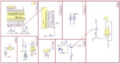
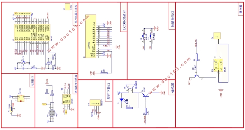
1.硬件电路原理图 29 [来源:http://think58.com]