
基于单片机的金属感应式智能循迹小车设计(含电路原理图)
1.无需注册登录,支付后按照提示操作即可获取该资料.
2.资料以网页介绍的为准,下载后不会有水印.资料仅供学习参考之用.
密 惠 保
基于单片机的金属感应式智能循迹小车设计(含电路原理图)(任务书,开题报告,论文14000字,电路原理图)
摘 要
本次设计方案采用的是基于STC89C52单片机的金属感应式智能循迹小车。本设计具有各个模块相对独立,便于维护和升级,而且成本低的特点。金属感应式智能循迹小车的特点是能自主识别金属,然后根据锡箔路线走向来执行稳定的寻迹行驶。小车系统的控制处理器采用的芯片是STC89C52单片机。采用接近开关作为金属感应器来采集轨迹的信息,然后传送给单片机进行处理,通过反馈结果来对小车的行驶方向进行控制。本课题在光电循迹的基础上,考虑到光电感应受到外界光线影响不稳定因素,采用金属传感进行升级处理,有效的避免的外界的干扰和环境的不稳定,提高了循迹小车的稳定性。
关键词:STC89C52 智能小车 金属循迹
Design of metal inductive smart tracking car based on SCM
Abstract
The design is based on the use of metal induction STC89C52 SCM smart car tracking. The design is relatively independent of each module, easy to maintain and upgrade, and the cost is low. The feature of a metal inductive smart tracking car is that it is able to identify metal independently, then carry out a stable tracing driving in accordance with the tinfoil route. The control processor of the car adopts the chip -- STC89C52 SCM. It uses proximity switch as metal inductor to collect information of the track, transmits the information to SCM for processing, and controls the driving direction through feedbacks of the results. On the basis of the photoelectric tracking, the issue effectively avoids the outside interference and the instability of environment, and improves the stability of the tracking car by taking the influence of outside light into account and using metal sensor to proceed upgrade processes. [资料来源:http://www.THINK58.com]
Key Words: STC89C52; smart car; metal tracking
[资料来源:www.THINK58.com]
目 录
摘 要 I
Abstract II
第一章 智能金属感应式循迹小车概述 1
1.1 国内外研究动态 1
1.2 课题的目的和意义 1
1.3 系统设计要求 2 [资料来源:THINK58.com]
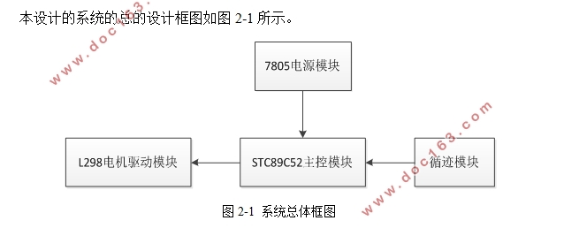
第二章 循迹小车设计总体方案 3
2.1 循迹小车系统构思 3
2.2 循迹小车设计概念图 3
2.3 硬件方案比较 4
2.3.1 车体设计 4
2.3.2 主控制器模块 4
2.3.3 循迹模块 5
2.3.4 电源模块 5
2.3.5 驱动模块 5
第三章 金属循迹小车硬件部分设计及状态分析 7
3.1 单片机控制电路 7
3.1.1 时钟电路 8
3.1.2 复位电路 8
3.2 循迹电路 9
3.2.1 循迹原理 9
3.2.2 循迹状态分析 10
3.3 驱动电路 11
3.3.1 L298引脚结构 11
3.3.2 电机驱动原理 13
3.3.3 驱动状态分析 15
3.4 电源电路 16
第四章 软件实现 18
4.1 软件程序总体设计 18 [版权所有:http://think58.com]
4.2 开发环境 18
4.3 模块化分析 19
4.3.1 循迹模块分析 19
4.3.2 驱动模块分析 21
第五章 测试方法与测试结果 25
5.1 测试方案 25
5.1.1 硬件测试 25
5.1.2 软件测试 26
5.2 测试问题解决 30
5.3 最终硬件实物图 31
结束语 35
参考文献 36
致谢 37
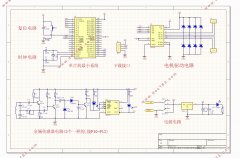
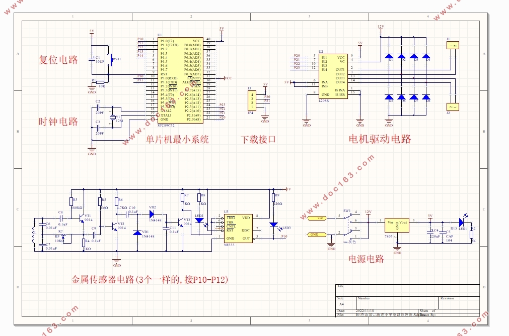
附录1:原理总图 38
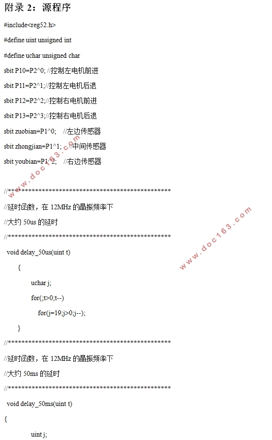
附录2:源程序 39