基于单片机的恒压恒流充电系统设计(硬件AD图,程序清单)

1.无需注册登录,支付后按照提示操作即可获取该资料.
2.资料以网页介绍的为准,下载后不会有水印.资料仅供学习参考之用.
密 惠 保
基于单片机的恒压恒流充电系统设计(硬件AD图,程序清单)(任务书,开题报告,外文翻译,论文说明书13000字,硬件AD图,程序清单)
摘要
随着现代世界电子产品的生产制作,各种电子产品层出不穷,无论是手机、汽车、还是电脑,衡量这些电子商品的质量好坏都有一个共同的标准,就是电池的性能。目前基本上市面的产品基本上都是可充电电池,但是能否高效安全快速的给电池充电还是一个难以攻克的难题。前段时间的三星手机爆炸事件,以及更前段事件的iphone充电时爆炸都是给人们敲响的一个警钟。
本文设计了一种基于单片机的恒压恒流充电系统设计,不同于市面上普遍的硬件保护芯片,本文采用51单片机和MOS管设计实现,硬件软件结合,通过调节单片机产生的PWM信号的占空比从而改变负载两端的电压,能够使得负载两端的电压电流基本保持恒定,实现稳定高效的充电过程,实现了设计目的。
关键字:恒压恒流;PWM;充电系统;单片机;MOS管
Abstract
With the production of electronic products in the modern world, a variety of electronic products after another, whether it is mobile phones, cars, or computers, measuring the quality of these electronic products have a common standard is the battery, the basic market fundamentals Are rechargeable batteries, but whether efficient and fast to the battery charge or a difficult to overcome the problem. Some time ago Samsung mobile phone bombings, as well as more previous events when the iphone charge explosion is to give people a wake-up call.
[资料来源:http://think58.com]
This paper designs a constant-voltage constant-current charging system based on single-chip microcomputer, which is different from the general hardware protection chip in the market. This paper adopts 51 single-chip and MOS tube design and hardware software, by adjusting the duty cycle of PWM signal generated by single chip microcomputer Than to change the voltage across the load, can make the load at both ends of the voltage and current remained constant, to achieve a stable and efficient charging process, to achieve the design purpose.
Key words:constant voltage;constant current;PWM;charging system single chip;MOS tube
[资料来源:www.THINK58.com]


目录
第1章 绪论 1 [资料来源:www.THINK58.com]
1.1课题研究的意义和背景 1
1.2充电技术的研究现状和国内外发展趋势 2
1.3本文的主要结构 2
第二章 充电理论基础及设计框架 3
2.1恒压恒流充电理论基础 3
2.2 PWM波技术 4
2.3 总体设计方案流程框架 5
2.4 经济性分析 5
2.5 本章小结 6
第3章 主要硬件设计 7
3.1微处理器的选择使用 7
3.2 驱动电路的方案选择 7
3.2.1 MOS管驱动模块方案 8
3.2.2图腾柱电路方案 8
3.2.3 CMOS门电路方案 9
3.3 电子开关的选择 10
3.4 传感器的选择 10
3.5 AD转换芯片的选择 11
3.6 驱动电路及负载调节电路 12
3.7 本章小结 12
第4章 整体软件设计 13
4.1 下位机程序整体流程 13 [资料来源:http://www.THINK58.com]
4.2 主要子程序流程介绍 14
4.2.1 PWM占空比调节程序 14
4.2.2 TM7705采样程序 14
4.2上位机软件总体设计 15
4.3 串口配置模块设计 16
4.4 数制转换模块设计 17
4.5 上位机前面板 17
4.6 本章小结 18
第5章 实验数据处理与误差 19
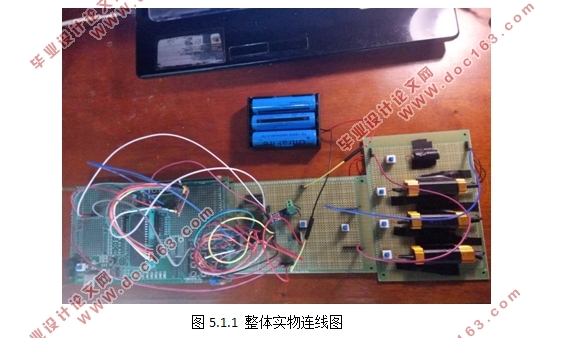
5.1 整体实物图 19
5.2 实验数据分析 20
5.2.1 调节占空比实验 20
5.2.2 不同负载值测量数据 22
5.3实物演示图 22
5.4 本章小结 23
第六章 结论 24
参考文献 25
附录 26
附录A 硬件电路图 26
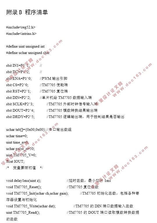
附录B 程序清单 26
致谢 27 [来源:http://think58.com]
上一篇:基于单片机的多伺服控制系统的设计
