多功能电气参数测试仪的设计(含电路图,Proteus仿真程序)

1.无需注册登录,支付后按照提示操作即可获取该资料.
2.资料以网页介绍的为准,下载后不会有水印.资料仅供学习参考之用.
密 惠 保
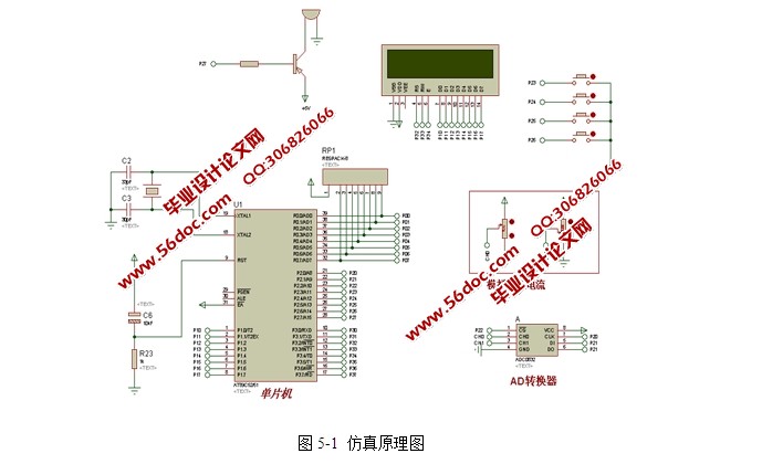
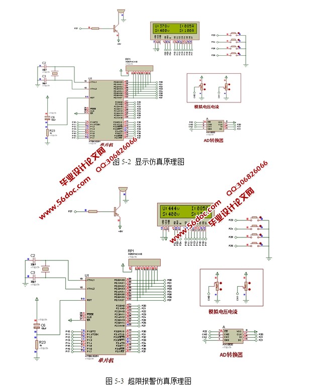
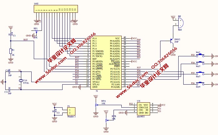
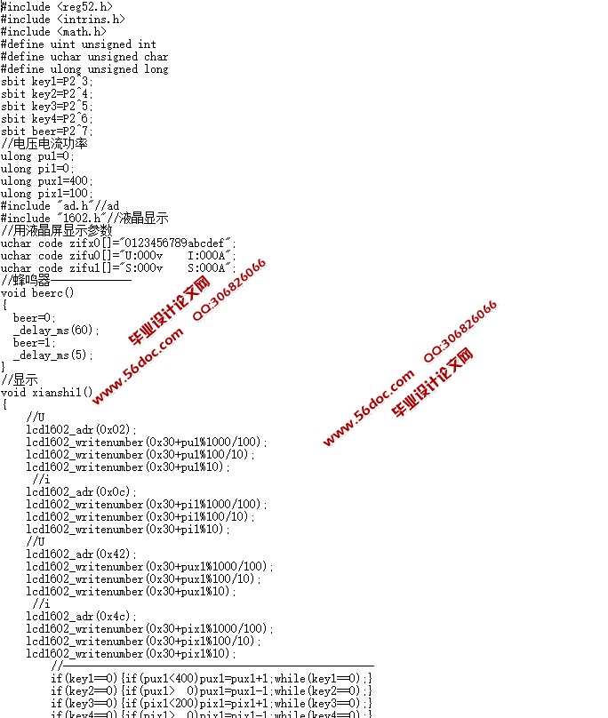
多功能电气参数测试仪的设计(含电路图,Proteus仿真程序)(任务书,开题报告,论文10000字,Proteus仿真程序)
摘要
本系统使用电压、电流变送器,结合ADC0832芯片及LCD1602液晶模块,通过STC89C52单片机进行控制,具体研究和设计了一款单相电气参数测量仪。 相对于传统的单相电参数测量仪,它具有精度高、可靠性强、功能强大及智能化等诸多优点。本测量仪表可以实时、准确测量交流电压和电流的有效值,并可通过按键设置电压、电流的报警上限值,当采集值大于设置上限值时,能够进行实时的报警。测量参数值可以液晶屏进行实时的显示。 经过仿真验证,本设计的实能够实现实时的交流电压采集、交流电流采集、电压和电流的报警上限设置和超限报警等功能。研究、设计此类仪表有利于减少企业、工厂及家庭用电浪费,更好的节约资源、保护环境,从而真正实现环境友好型社会。
关键词:单片机;变送器;液晶显示
Abstract
The system uses the voltage, current transmitter, combined with chip ADC0832 and LCD1602 module, through the microcontroller STC89C52 control, specific research and design the a single-phase electrical parameter measuring instrument. Compared with the traditional single-phase electric parameter measuring instrument, it has high precision, strong reliability, powerful and intelligent advantages. The measuring instrument can real-time, accurate measurement of AC voltage and current effective value, and can set the button voltage, current alarm limit value, when the acquisition value is greater than the limit value is set to carry out real-time alarm. Parameter measurement value of LCD screen for real When the display. It is proved by the simulation and the design can realize the real-time AC voltage sampling, AC current acquisition, voltage and current alarm upper limit setting and over limit alarm functions. Study for the design of this kind of instrument is to reduce the enterprise, factories and household electricity waste, better resource conservation, environmental protection, so as to realize environmental friendly society.
[资料来源:http://www.THINK58.com]
Key words: single chip microcomputer; transmitter; liquid crystal display
本课题是要实现一种基于单片机的多功能电参数测量仪系统。利用单片机、交流电流电压传感器和交流电压传感器相结合,实现供电线路对流电压监控、报警等功能的设计。本设计主要研究内容如下:
1)显示功能。供电线电流、电压、频率的显示;
2)按键输入功能。实现上限报警电压、电流设置功能;
3)测量功能。通过采集传感器的输出,实现对供电线电压、电流的测量;
4)利用Protel软件进行系统硬件的原理设计;
5)利用Keil软件进行C语言编程,实现单片机对外部硬件的驱动,使用Protues软件进行可行性仿真实验;
本系统设计的选用8位STC89C52单片机作为主控芯片。系统设计采用模块化思想设计,本系统由单片机最小系统、传感器检测模块、LCD液晶显示模块、按键模块、电源模块和蜂鸣器报警模块八个模块主成。
1)单片机是实现对各模块的控制;
2)传感器模块模块用于供电线的电流、电压和频率值;
3)LCD模块显示检测的电压和报警电压;
4)按键模块用于切换不同的系统显示界面;
5)电源模块为系统各个模块提供工作电源;
[来源:http://think58.com]
6)当采集的电流电压值超限时,通过蜂鸣器发出报警提示音。
[资料来源:THINK58.com]


目录
摘要 1
Abstract 2
目录 3
1引言 5
2系统整体设计方案 7
2.1研究主要内容 7
2.2方案论证 7
2.2.1主控器器件方案论证 7
2.2.2传感器选择方案论证 8
2.2.3显示器选择方案论证 8
2.2.4按键控制方式方案论证 9
2.2.5供电方式选择方案论文 9
2.4系统基本框架 9
3系统硬件电路设计 11
3.1电源模块 11
3.1.1器件选型 11
3.1.2 电源电路设计 11
3.2单片机最小系统 11
3.3 传感器采集电路设计 13
3.3.1电流变送器介绍 13
3.3.2交流电流采集电路设计 13
3.3.3电压变送器介绍 13
3.3.4电压变送器采集电路设计 14
3.4 按键采集电路设计 14
3.6 显示模块设计 15
3.6.1 LCD1602液晶介绍 15
3.6.2 显示电路设计 15
3.7 报警电路设计 16
4 系统软件设计 17
4.1 主程序设计 17
4.1.1 主程序清单 17
4.2 显示程序设计 18
4.2.1 显示程序清单 19
4.3 控制程序设计 20
4.3.1 控制程序清单 20
5系统仿真 22
5.1系统仿真 22
5.1.1 Proteus软件介绍 22
5.1.2 Proteus功能建立步骤 22
5.1.3 仿真原理图设计 22
5.1.4仿真原理介绍 23
5.1.5运行结果分析 23
总结 26
致谢 28
参考文献 29
1引言 [资料来源:http://THINK58.com]
