
��Ȧ����߸���ģ�����(��CADͼ,SolidWorks��ά���ͼ,UG��άװ��ͼ)

1.����ע���¼,֧��������ʾ�������ɻ�ȡ������.
2.��������ҳ���ܵ�Ϊ,���غ���ˮӡ.���Ͻ���ѧϰ�ο�֮��.
�� �� ��
��Ȧ����߸���ģ�����(��CADͼ,SolidWorks��ά���ͼ,UG��άװ��ͼ)(����˵����13000��,CADͼ11��,SolidWorks��ά���ͼ,UG��άװ��ͼ)
ժ Ҫ
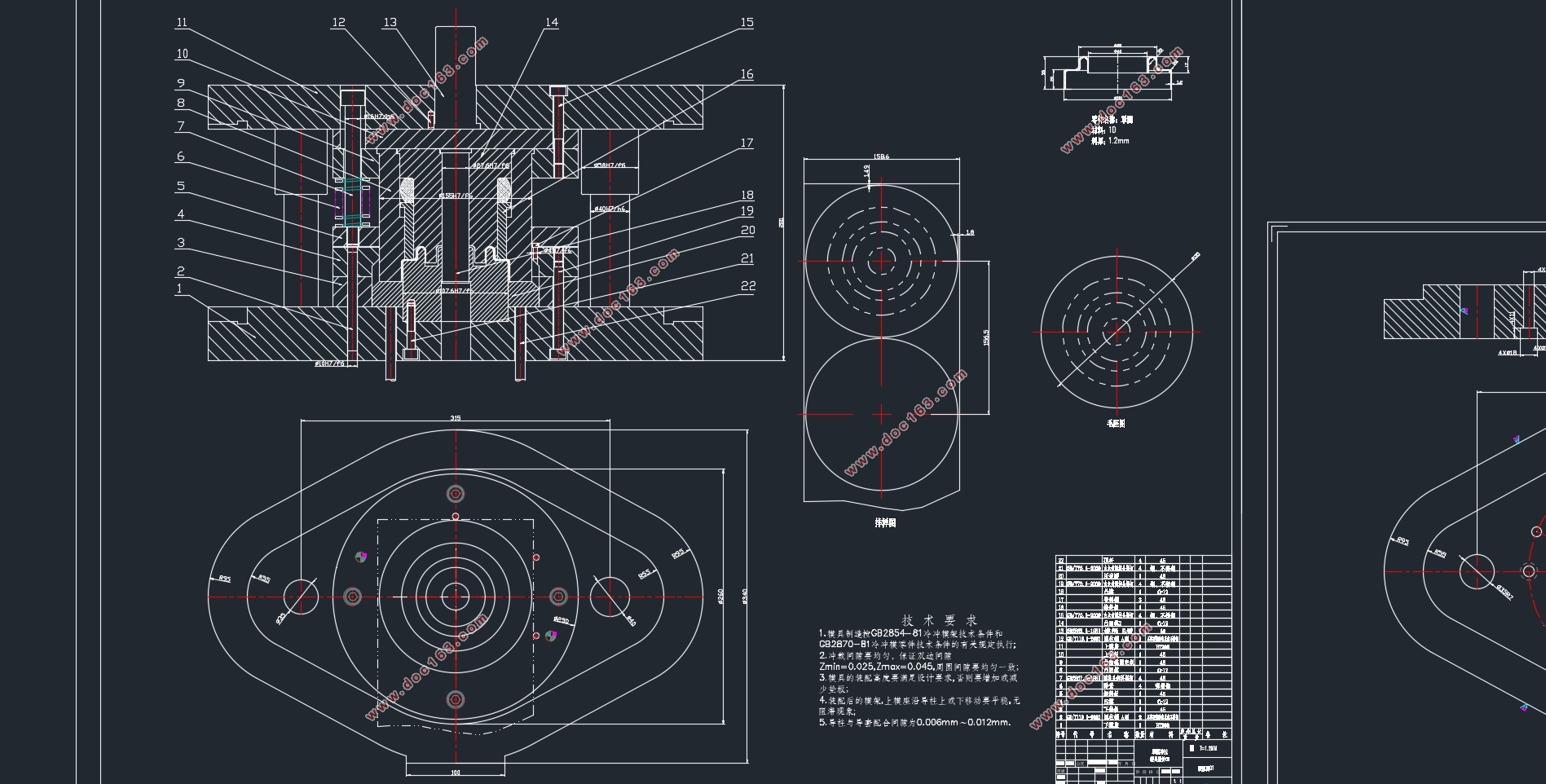
������Ҫ��������ʵ�ʳ���������Լ�������Ȧ��������������ơ�ͨ���Գ�ѹ����ʵ�ʽ�ģ����������������ͨ�����ַ���֮��ıȽϣ����IJ��ø���ģ�߽ṹ��ģ�������������ϡ���ס����죬���ߵȹ����ҶԱ�������������IJ��ϡ��ߴ硢��״�;��Ƚ��г�ѹ���շ�������Ƴ�����������ͼ����ģ������е���Ҫ�Ĺ�����̽���ģ����ƣ�����˸���ģ�ߵ���Ҫ�ṹ�����ڷ��װ�ģ�߽����˽ṹ��������ƣ�����ṹ�ߴ�����˺����ķ������㣬ȷ����������ṹ����������ͨ�������Ľṹ����Լ��ɿ��ķ������㣬ʹ����Ƶ�ģ���ܹ��㷺�������ڽϴ�����ļӹ����죬ͬʱ�ܹ������ڽṹ���ӵij�ѹ�����ͨ������ʱ�䣬�����˺����Ľṹ��ƣ�����˲�Ʒ��������
���ո���ģ�ߵĹ��շ������㣬��ģ�ߵ��㲿�����к�������ƺ�ѡ�á�������ж�ģ�ߵ�����ṹ������ƣ���������ģ�����������ס���塢�̶��塢���ϰ塢ж�ϰ�ȵ������ѡ�á�ͨ�������ϲ���ļ��飬ȷ�����յ������ԺͿ����ԣ��ڽ���ѹ������ѡ�ú�ģ�߲��ϵ�ѡ�����տ����������ģ�ߵĻ��ơ�����������ѧ�����ڻ��ͨ������Ҳ����ѧϰ���µ����˼·�����˼�룬�˽��˸�������ģ�ߵ���ƣ���������Ұ�� [��Ȩ���У�http://think58.com]
�ؼ��ʣ���Ȧ����ƣ�ģ�� �����㣻��ͼ��У��
Abstract
This paper mainly from the actual production, combined with their understanding of the ring parts for the design. Through the actual modeling of stamping parts, analysis of each process, through the comparison of various programs, this paper adopts the compound die structure, die set up blanking, punching, stretching, flanging and other processes. The material, dimension, shape and precision of the part are analyzed, and the reasonable layout drawing is designed. The main structure of the compound die is designed, the structure of the flanging and concave-convex die is analyzed and designed, and the reasonable structure size is analyzed and calculated, the overall structural characteristics are determined. Through reasonable structure design and reliable analysis and calculation, the designed die can be widely applied to the processing and manufacturing of larger parts, and also can be applied to the stamping parts with complex structure, the reasonable structure design is adopted and the quality of the product is improved. Finally, according to the mold process analysis and calculation, the mold parts for reasonable design and selection. In the design of the overall structure of the mold design, including the upper and lower mold base, guide pillar bushing, backing plate, fixed plate, guide plate, discharge plate and so on. Through the inspection of the above steps, to determine the integrity and feasibility of the process, in the selection of press and die material selection, the final can complete the whole die drawing. Not only test the ability of students to understand, but also learn from the new design ideas and design ideas, understand more parts and mold design, broaden the vision. [��Դ��http://think58.com]
Key words: Ring; design; mold; calculation; drawing; Check
�����ѹ���շ���
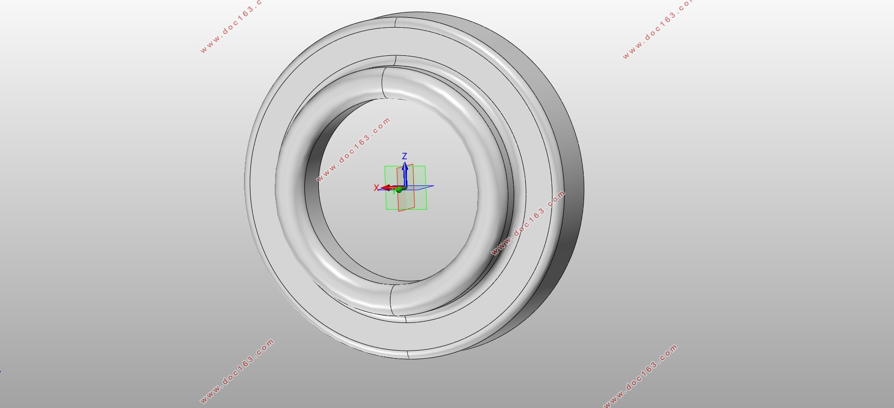
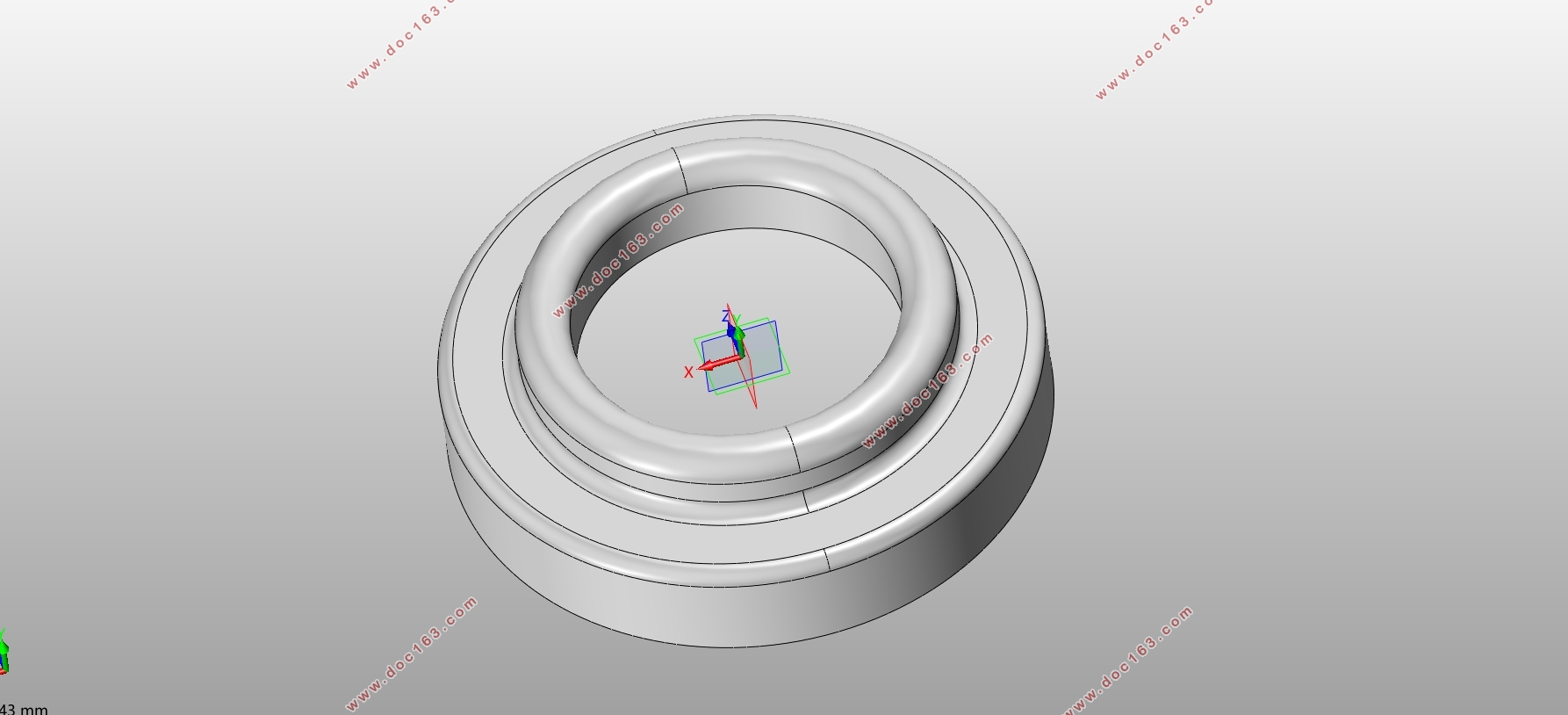
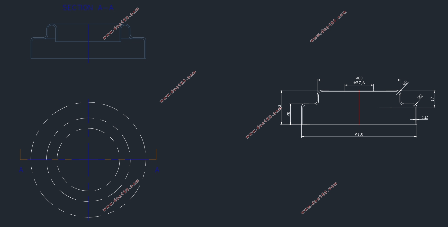
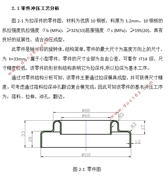
ͼ2-1Ϊ����������ͼ������Ϊ����10�ְ壬�Ϻ�Ϊ1.2mm��10�ְ�Ŀ���ǿ�ȿ���ǿ�� σb (MPa)��≥325(33)����ǿ�� σs (MPa)��≥195(20)���������õ���չ�ԣ��ʺϳ�ѹ���͡�
���������ԳƵ���ת�壬�ṹ����������ߴ�Ϊ�߶ȷ����ϵijߴ磬Ϊh=33mm������С�����������ijߴ�ȫ��Ϊ���ɹ���ɿ���IT14�����ߴ羫�Ƚϵͣ����������״�ͽṹ������Ϊ�����,��������Ϊ��������
ͨ��������ṹ������֪���������Ҫͨ������ģ�߳��ͣ����ɻ�óߴ羫�ȡ��ɿ���ͨ�������������߸���ģ��ɡ���˿�֪������Ļ�����ѹ����Ϊ�����ϡ����죬��ף����ߡ�
[������Դ��http://THINK58.com]

[������Դ��http://think58.com]
Ŀ¼
ժ Ҫ 1
Abstract 2
Ŀ¼ 3
��һ�� ���� 5
1.1�� �� 5
1.2ģ�߹�ҵ�ڹ����е����� 5
1.3ģ�߷�չ�ſ� 6
1.4 �����о�����Ҫ���ݺ����� 7
�ڶ��� ��ԵͲ�μ�����շ��� 9
2.1 �����ѹ���շ��� 9
2.2 �ⶨ���շ��� 9 [������Դ��http://think58.com]
2.2.1 ����ë���ߴ� 9
2.2.2 ��Ȧ��������������� 11
2.2.4�ⶨ���շ��� 13
������ ��Ҫ���ղ����ļ��� 14
3. 1 ����������ȷ�� 14
3. 2 ��ߵ�ѡȡ 15
3.3���ϲ��ࡢ���Ͽ��ȼ����ϼ����� 16
3.4 ѹ�����ĵļ��� 18
3.5���������ѹ����ѡ��ѹ���� 18
3.5.1 ���㹤���� 18
3.5.2 ж�������Ƽ������Ͷ������ļ��� 20
3.5.3ģ���ܳ�ѹ������ 21
3.5.3 ��ѡѹ���� 21
3.6 ��������ģ�пڳߴ���� 22
������ �����������߸���ģ��� 26
4.1ģ�Ͱ�ģ��� 26
4.1.1 ģ 26
4.1.2 ��ģ 27
4.1.3 ��ģ 28
4.2ж�Ϻ�ѹ�߷������ 29 [��Ȩ���У�http://think58.com]
4.3��λλ�������� 30
4.4��������ѡ�� 31
4.5ģ�ܼ����������� 32
4.6ģ�߹������� 33
4.8 ģ�� 33
4.9 ж��װ�� 33
4.9 ����֧����̶���� 34
4.9.1ģ�̶��� 34
4.9.2��� 34
4.9.3 ���̼� 34
�ܽ� 35
��л 36
����� 37
��һƪ���п����������������ѹģ�����(��CAD���ͼװ��ͼ,UG��άͼ)
��һƪ�������൲Ƭ��ѹģ����Ƽ��˶�����(��CAD���ͼװ��ͼ,UG��άͼ)