名爵汽车底盘连接片连续模设计(含CAD零件图装配图)

1.无需注册登录,支付后按照提示操作即可获取该资料.
2.资料以网页介绍的为准,下载后不会有水印.资料仅供学习参考之用.
密 惠 保
名爵汽车底盘连接片连续模设计(含CAD零件图装配图)(选题审题表,任务书,开题报告,论文说明书7000字,CAD图12张)
摘 要
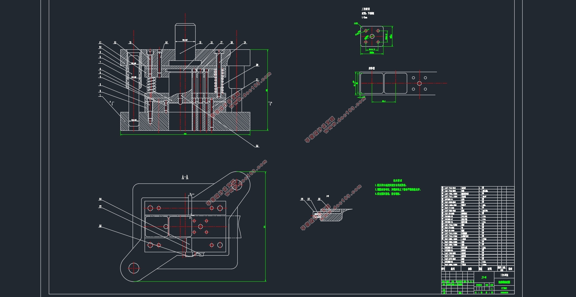
随着全球的互通发展我国经济的蒸蒸日上,各行各业的发展都离不开模具,尤其在汽车,机械等领域方面我国取得了巨大进步,模具制造业在我国的发展已经从原来的低谷逐渐上升。本次课题是有关汽车底盘连接片连续模设计及制造的研究,概括起来其内容主要有对模具行业发展的分析、连续模在模具制造中的地位以及作用、UG技术的简介、冲压模具设计的基本方法、模具工艺分析以及模具零件和整体设计。这次设计的汽车底盘连接片连续模,该类模具是多任务冲模,有良好的工作效率,此零件在冲压环节精度高。本次设计的连续模主要的工序是冲孔和落料两部分,其中就需要对模具的压力机的选取,压力中心的计算,冲裁力的计算,凸凹模尺寸以及模具模架尺寸的计算和选用。其次运用UG软件对模具进行结构分析,画出毛坯进行加工。
关键词:连续模;尺寸计算;零部件选用;UG制图;
ABSTRACT
With the development of global connectivity, China's economy is booming, and the development of all walks of life is inseparable from mold, especially in the fields of automobile, machinery and so on. China has made great progress in the development of mold manufacturing industry in China has gradually risen from the original trough. This topic is about the research of the design and manufacture of the continuous die for the connecting piece of the automobile chassis, which includes the analysis of the development of the die industry, the position and function of the continuous die in the die manufacture, the introduction of UG technology, the basic method of the stamping die design, the die process analysis, the die parts and the overall design. The continuous die for connecting piece of automobile chassis designed in this paper is a multi task die with good working efficiency and high precision in stamping process. The main process of the design of the continuous die is punching and blanking, which requires the selection of the die press, the calculation of the pressure center, the calculation of the punching force, the calculation and selection of the convex and concave die size and the die frame size. Secondly, using UG software to analyze the structure of the mold, draw the blank for processing. [资料来源:www.THINK58.com]
Key word:Continuous die; Dimension calculation; Parts selection; UG drawing;
冲压工艺分析
2.1材料分析
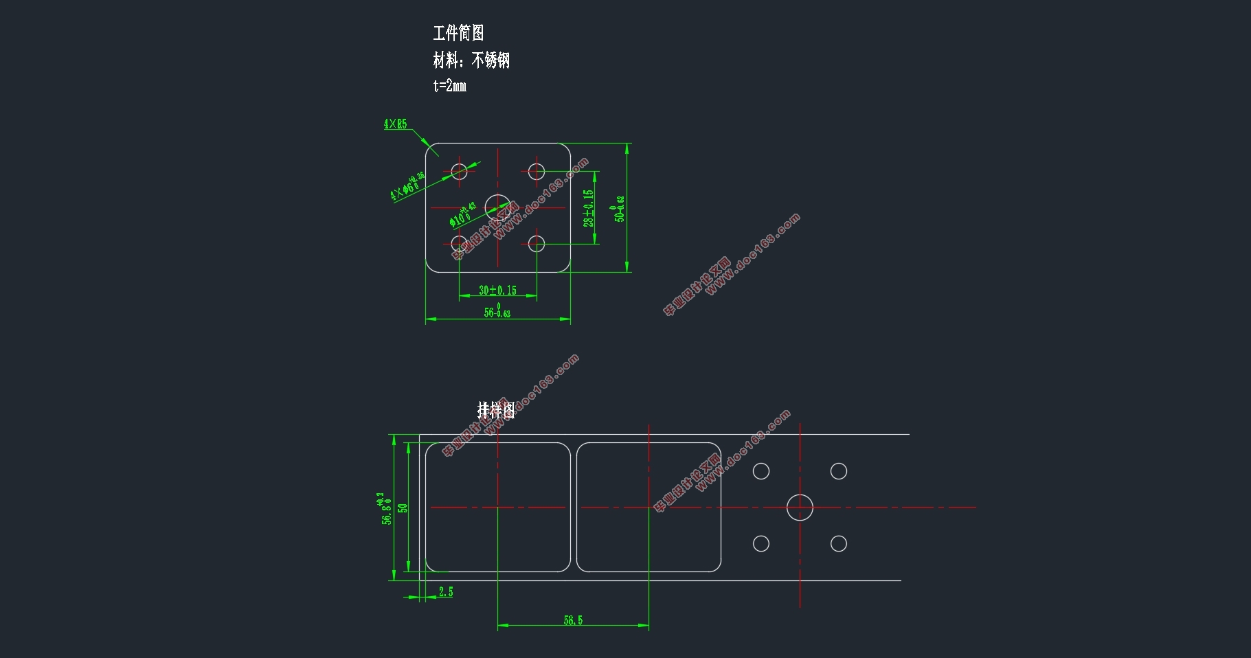
零件名称:名爵汽车底盘连接片
材料:不锈钢,t=2mm
特点:冲裁件是不锈钢,具有良好的超低温韧性和耐腐蚀性【6】。
由图2-1可知,此冲裁件的形状对称,结构比较简单,从表2-1两孔中心距离可知,φ6mm两孔中心距为±0.15,零件图未标注公差为IT14。
表2-1 两孔中心距公差
材料厚度t/mm 孔距基本尺寸/mm
一般精度 较高精度
<=50 50~150 150~300 <=50 50~150 150~300
<=1 ±0.10 ±0.15 ±0.20 ±0.03 ±0.05 ±0.08
>1~2 ±0.12 ±0.30 ±0.30 ±0.04 ±0.06 ±0.10
>2~4 ±0.15 ±0.25 ±0.35 ±0.06 ±0.08 ±0.12
>4~6 ±0.20 ±0.30 ±0.40 ±0.08 ±0.10 ±0.15
2.2.冲压工艺方案设计
冲压工艺设计也是模具制造中很重要的一部分。冲压工艺方案设计的好坏决定了该零件生产的经济性、稳定性以及生产效率的高效性,本次冲裁件形状轮廓较小,尺寸精度不高等特点【7】。主要是冲孔、落料两个工序,有三种可行方案:
方案一是采用但工序模具的生产方法,第一步先冲孔,然后在进行落料处理,单工序模具虽然结构简单,但是在加工时需要两幅模具,这样的加工方案就大大的提高了加工成本,经济效益也低下。方案二则是采用复合模具生产,冲孔落料复合冲压,这样虽然提高了生产效率但是加工精度要求比较高。方案三是采用连续模,冲孔落料连续冲压,综合比较因为方案三即保留了方案一单一模具的好处,模具设计简单同时生产效率也高,所以采用方案三最合适。 [资料来源:THINK58.com]
该连续模一共有两个工位,第一个工位完成工件上五个孔的冲孔工序,第二个工位完成外轮廓的落料工序。该模具的结构为弹性卸料、自然漏料的方式,并用始用挡料销对条料进行定位。
[资料来源:http://THINK58.com]


目录
第一章 绪论 1
1.1当代模具发展 1
1.2连续模概念.................................................................................................................1
1.3连续模特点.............................................................................................. ..................1
1.4UG加工技术简介................................................................................... .... .................1
第二章 冲压工艺分析 2
2.1材料分析 2
2.2冲压工艺方案设计......................................................................................................2
第三章 排样设计及确定压力中心 4
3.1排样设计 4
3.1.1计算条料宽度和送进距离 4
3.2压力中心的确定 5
第四章 计算工序力及选择压力机 6
4.1工序力 6
4.2选择压力机 7
第五章 模具尺寸计算及零部件选用 9
5.1确定工件尺寸公差 9
5.1.1计算凸模、凹模刃口尺寸 9
5.1.2计算中心距尺寸 10
5.2主要零件外形尺寸的计算及选用 11
5.2.1确定凹模外形尺寸及刃口形式 11
5.2.2确定卸料板、凸模固定板、垫板、导料板厚度尺寸 11
5.3凸模设计 13
5.3.1凸模形式 13
第六章 模架、模柄的选用 14
6.1模架的选用 14
第七章 凹模加工 16
7.1 确定55.69mm×49.69mm的工序尺寸和加工余量 16
7.2确定φ6.30mm的工序尺寸和加工余量 16
7.3确定φ10.34mm的工序尺寸和余量 16
7.4 UG加工 17
结束语 19
致 谢 20
参考文献...........................................................................20 [版权所有:http://think58.com]
上一篇:方形盒注塑模具设计(含CAD零件图装配图,UG三维图)
下一篇:名爵汽车底盘连接片倒装复合模具设计(含CAD零件图装配图)
