
空气室下体注塑模设计(含CAD零件图装配图)
1.无需注册登录,支付后按照提示操作即可获取该资料.
2.资料以网页介绍的为准,下载后不会有水印.资料仅供学习参考之用.
密 惠 保
空气室下体注塑模设计(含CAD零件图装配图)(开题报告,文献综述,设计说明书10000字,CAD图8张)
The air chamber body mold
摘 要
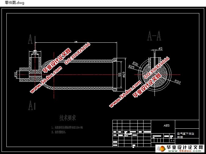
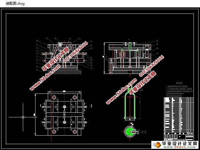
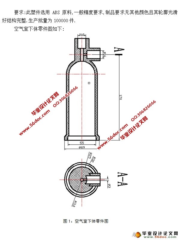
空气室下体的主要框架是回转体,尺寸适中,结构较为复杂。为了大批量生产此产品,在注塑此产品的过程中,零件决定需要用侧向抽芯机构,动模开模过程中斜导柱带动滑块滑动从而实现侧向抽芯和开模强制脱模动作。推杆在开模完成后在顶杆作用下推出零件。经过考虑该零件适用于一模两腔,因此在浇注系统上设计了测浇口,和分流道等。应零件尺寸较高,为避免开模行程无法满足取件要求从而采用热流道的方式浇注。排气系统由于推杆与模板及分型面与模板之间都拥有空隙的原因可以不做考虑。空气室下体采用ABS材料成型,压力较大,但用楔紧块保证了空气室下体模具的可靠性。
关键词:空气室下体; 注塑模; 测抽芯; ABS
ABSTRACT
The main frame of the lower body of the air chamber is a revolving body with moderate size and complex structure. In order to mass production of this product, in the process of the injection molding products parts decided need with side core pulling mechanism, dynamic mould opening process in the slanting guide pillar drives the sliding block to slide in order to achieve lateral core pulling and opening force releasing action. The push rod in the mold after parts of the push rod under the action of. After considering the part can be applied to a mold two cavity, the gating system is designed with the potential gate, and the shunt channel, etc.. Should part size is high, in order to avoid opening stroke can not meet the requirements to take the way of pouring hot runner. Because of the gap between the push rod and the parting surface, there is no need for additional design of exhaust system. The lower body of the air chamber is made of ABS material, the pressure is large, but the wedge block ensures the reliability of the lower body of the air chamber. [来源:http://www.think58.com]
Key words: The air chamber body; injection mold; measuring core pulling; ABS
[资料来源:http://www.THINK58.com]
目 录
绪 论 1
1. 产品工艺性分析 2
[资料来源:http://think58.com]
1.1 材料性能 2
1.2 ABS树脂主要性能参数 3
1.3 成型特性及条件 3
2. 初选注射成型机的型号规格 4
2.1 确定模具基本结构 5
3. 模具结构设计 5
3.1 确定型腔数目及配置 5
3.2 选择分型面 5
3.3 确定浇注位置和系统尺寸 6
3.4 确定凹模、凸模的构成及加固方法 8
3.5 确定顶出机构类型 8
3.6 侧向抽芯机构的设计 9
3.7 确定导向机构 10
3.8 排气机构 10
3.9 温度控制方式 11
3.10 模具材料 11
4.定制模具装配图 12
4.1 选取标准模架 12
5. 计算凸模、凹模的尺寸 13
5.1 计算凸模、凹模的尺寸 13
5.2 计算凹模侧壁厚度与底板厚度 14
6. 注射机有关参数的校核 15
6.1 型腔数量和排列形式的最后确定 16
6.2 浇注系统的设计与计算 16
6.3 成型零件结构的确定 20
6.4 排气与引气系统结构的确定 20
6.5 冷料穴的设计 20
6.6 模具结构形式的确定 21
7. 主要零部件的设计计算 22
7.1 成型零件工作尺寸计算 22
总 结 25
致 谢 26
参考文献 27
[资料来源:http://THINK58.com]
上一篇:电子产品的端盖Φ20顶盖冲压工艺及模具设计(含CAD图)
下一篇:外环落料,冲孔,翻边,复合模具设计(含CAD零件图装配图)