斜插座注塑模设计与加工(含CAD零件图装配图)

1.无需注册登录,支付后按照提示操作即可获取该资料.
2.资料以网页介绍的为准,下载后不会有水印.资料仅供学习参考之用.
密 惠 保
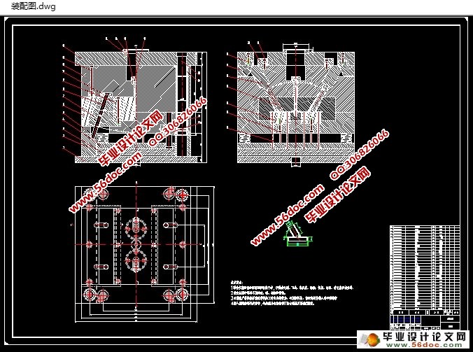
斜插座注塑模设计与加工(含CAD零件图装配图)(文献综述,设计说明书11000字,CAD图11张)
摘 要
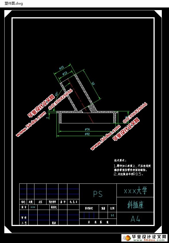
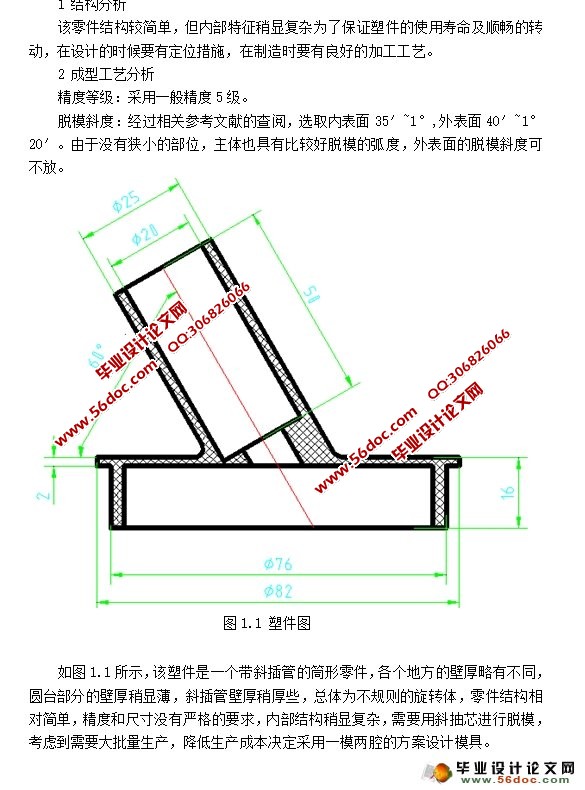
本文是关于斜插座塑料件设计,塑件结构较简单,尺寸和精度方面没有较高的要求,内部结构稍有复杂,决定使用斜抽芯脱模。通过对塑件的形状尺寸和工艺性分析,在尽可能使模具结构简化并且达到尺寸精度,表面粗糙度表面制量等的要求下选择注射方法。制作出工艺卡片,对模具的结构进行设计,确定型腔数目,分型面,浇口位置等。经过对生产成本的分析和对生产效率的考虑,本模具采用一模两腔。然后开始绘制模具结构草图,对相关数据进行校核,对存在的问题进行修正,运用CAD绘制出模具总装配图,运用分析软件对浇注系统,冷却系统等进行分析,成型件的工艺性得到较高的保证。再将冷却和浇注系统合理的加进总装配图进行校核,更正。最后绘制出要加工零件工作图。
关键词:成型工艺; 结构设计; 型腔制
Abstract
This paper is about the design of the plastic part of the oblique socket, the structure is simple, the size and precision is not high requirements, the internal structure is somewhat complex, decided to use the inclined core pulling. Through the analysis of the shape and size of the plastic parts and the process, the mold structure is simplified and the size accuracy is achieved, and the surface roughness of the surface roughness is chosen. Make the craft card, the structure of the mold design, determine the number of cavity, parting surface, gate location and so on. After the analysis of the cost of production and the consideration of the production efficiency, the mould adopts a mold two cavity. And start drawing die structure sketch, the relevant data check to amend the existing problems, use CAD to draw the mold assembly diagram, were analyzed by using analysis software of gating system, cooling system, molding process and get a higher guarantee. Then the cooling and pouring system is reasonable to add the total assembly drawing to check, correct. At last, draw the working drawings of the parts to be processed. After the guidance of teachers to check and guide the final correction and modification, make as far as possible a good design. [资料来源:http://www.THINK58.com]
Key words:molding process; structure design; cavity system
[来源:http://think58.com]


目 录
绪论 1
第一章方案论证 2 [资料来源:THINK58.com]
1.1塑件的结构工艺性分析 2
1.2成形工艺分析 3
1.3生产规模 6
第二章斜插座注塑模结构设计 6
2.1成型零件设计 6
2.1.1分型面位置的确定 7
2.1.2成型零件结构分析 8
2.1.3成型零件材料的选用 8
2.1.4 成型零件的结构设计 8
2.1.4.1定模结构设计 8
2.1.4.2动模和型芯结构设计 8
2.1.5 成型零件工作尺寸计算 9
2.1.5.1型腔径向尺寸 9
2.1.5.2 型腔深度尺寸 10
2.1.5.3 型芯径向尺寸 11
2.1.5.4 型芯高度尺寸 11
2.2浇注系统设计 12
2.2.1 主流道的设计 13
2.2.2 分流道的布置形式 14
2.2.3分流道的形状 15
2.3推出机构的设计 15
2.3.1推板的推动原理和草图 15 [版权所有:http://think58.com]
2.3.2推板的设计要求 16
2.4排气系统 16
2.5冷却系统的设计 16
2.5.1冷却管道直径 16
2.6模架与注射机的选择 17
2.6.1模架的选择 17
2.6.2注塑机的选择 17
2.6.2.1注射量的计算 17
2.6.2.2塑件和流道凝料的投影面积计算 17
2.6.2.3锁模力的计算 17
2.6.3 注塑机参数的校核 18
2.6.3.1 注射压力的校核 18
2.6.3.2 锁模力的校核 18
2.6.3.3模具外形尺寸校核 18
2.6.3.4 喷嘴尺寸及定位圈尺寸校核 18
2.6.3.5开模行程的校核 19
2.7模具结构草图 19
2.7.1定模结构图 19
2.7.2动膜结构图 20
2.7.3模具总结构图 21
2.8注射模动作过程分析 22
第三章成型零件加工工艺 23 [版权所有:http://think58.com]
3.1 加工路线 23
3.2数控编程 23
总结 27
致谢 28
参考文献 29
[版权所有:http://think58.com]
上一篇:Φ23顶盖冲压工艺及模具设计(含CAD零件图装配图)
