
����68m+120m+68m���Ӵ����ϲ��ṹ�����������(��CADͼ)
1.����ע���¼,֧��������ʾ�������ɻ�ȡ������.
2.��������ҳ���ܵ�Ϊ,���غ���ˮӡ.���Ͻ���ѧϰ�ο�֮��.
�� �� ��
����68m+120m+68m���Ӵ����ϲ��ṹ�����������(��CADͼ)(������,���ⱨ��,���ļ�����19000��,CADͼ34��)
ժ Ҫ
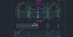
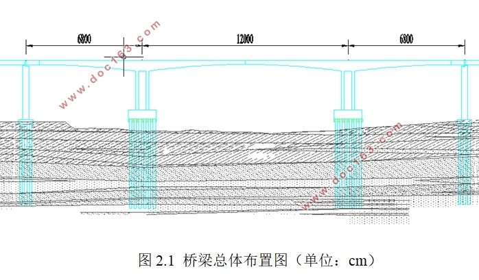
�����ΪԤӦ�������������չ���,ȫ��Ϊ256m��������68m+120m+68m���ɣ�������ʽ�������ͽ��棨���䵥�ң�����ƺ��ر�Ϊ��·-I�����أ�����ʩ�����ù��������۶Գ�ʩ��������δ�����²��ṹ���Ŷա���̨������������ԤӦ��������ԤӦ������ƣ��ص�����ϲ��ṹ���������������
�����չ����ŵ�ܶ࣬�����������������ŵ��ص㣬���кܶ��������Ų��ɱ�����ص㣬���Խ���������̽���ϵ���նȴ���С��˫���ڶս�ʡ֧���������Ż��˽ṹ���������ܵȡ�
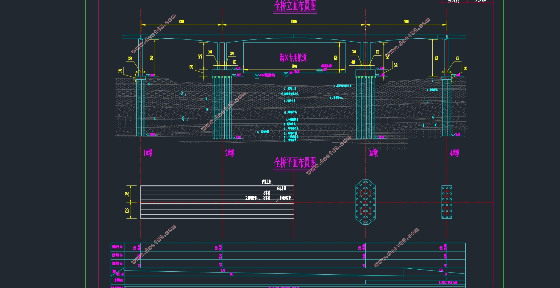
�ڽ�����Ƶ�ʱ����˱Ƚ϶�Ĺ���ʵ����Ҳ�ο��˴������������ϣ��Խṹ������������˱Ƚ���ϸ�ķ������о�������MIDAS/Civil������������ģ�ͣ�������õ��䵥�ҽ��棬��������߶Ȳ��ö��������߱仯������֧�㴦���6.7m��������С2.7m�������Ⱦ�Ϊ25cm��Ϊ�˼�Сʩ���Ѷȣ�����������չ��ŵ������ص㣬�װ��ȳ�ֱ�����Ա仯������֧������м�С������֧�㴦Ϊ���0.7m��������СΪ0.3m��������Ҳ��ֱ�����Ա仯������֧������м�С������֧�㴦Ϊ���0.7m��������СΪ0.4m������ģ�ͺ���������MIDAS/Civil������ģ�ͽ�����ϸ��������,Ȼ�����ԤӦ������������������ԤӦ�����������������ƽ���ij�������������״̬����������������Ƚ��л�������ԤӦ������ͼ��ԤӦ������ͼ�������ſ粼��ͼ������ָ����ʩ������ͼ��ԤӦ����������ͼ�ȣ�Ȼ��������ķ��룬���༭��Ƽ���˵������ĵ������� [������Դ��THINK58.com]
�ؼ���: ԤӦ�������������չ��ţ�����ʩ��������������
Abstract
The design of the prestressed concrete continuous rigid frame bridge, a total length of 256m, by the three-span (68m +120m +68 m) composition, cross-section of the box-type cross-section (single-box single room), designed load-based highway-I load Construction of cantilever symmetry with cantilever construction in beam construction. In this paper, no design of the lower structure (piers, cap and pile foundation), transverse prestressing and vertical prestressing is carried out, and the design and calculation of the superstructure are mainly completed.
There are many advantages of continuous rigid bridge, which not only retains the characteristics of continuous beam bridge, but also has many unmatched characteristics of continuous beam bridge, such as the ability of crossing, the consolidation system of pier and beam, the stiffness is big, the deformation is small, The number of seats, optimize the structure of the force performance. [������Դ��www.THINK58.com]
In the design of the time, drawing on the more examples of engineering, but also refer to a large number of literature, the structure of the force carried out a more detailed analysis and research. The bridge model was established by using MIDAS / Civil software. The cross section of single section was adopted. The height of the main section was double parabola, and the maximum distance was 6.7m from the fulcrum to the minimum of 2.7m and the thickness of the roof was 25cm. In order to reduce the difficulty of construction, combined with the characteristics of the continuous rigid frame bridge, the thickness of the bottom plate is linearly changed from the middle fulcrum to the mid-span, from the maximum point of 0.7m to the minimum of 0.3m.After the model is built, the detailed internal force analysis of the model is carried out by using MIDAS / Civil software. Then, the number of prestressed steel beams is estimated and the prestressed steel beam is arranged. Finally, the bearing capacity and performance status of the control section are checked.After the internal force analysis is completed, the longitudinal prestressing section diagram, the prestressed layout diagram, the main bridge bridge cross-layout diagram, the main bridge guiding construction step diagram, the prestressed steel beam large sample map, etc., and then the foreign translation, the final editing Design calculations and documentation.
Key words: prestressing concrete continuins frame bridge; cantilever construction;analysis of internal forces.
[������Դ��www.THINK58.com]
Ŀ¼
��1�� ���� 1
1.1�����չ��ŵķ�չ 1
1.1.1���ⷢչ 1
1.1.2���ڷ�չ 1
1.2���ͷ�����ѡ 2
1.2.1������ƵĻ������� 2
1.2.2������ѡ 2
��2�� �������岼�ü�����ߴ��ⶨ 4
2.1������ݼ��������� 4
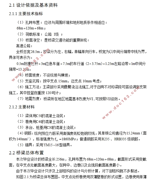
2.1.1��Ҫ����ָ�� 4
2.1.2��Ҫ���� 4
2.2�������岼�� 4
2.3����ߴ��ⶨ 5
2.3.1��������߶� 5
2.3.2������ 6
2.3.3������ 6
2.3.4�װ��� 6
2.3.5��֧��Ϳ��н��沼�� 6
��3�� ����ģ�͵Ľ��� 8
3.1���� 8
3.2����ģ�� 9
3.2.1���ڶεĻ��� 9
3.2.2���Ϲ�� 10
3.2.3��������Ķ����Լ������߽����������� 11
3.2.4�������ص����� 12
3.2.5ʩ���εĶ��� 13
3.2.6���ģ�� 14
��4�� �����ṹ�������� 15
4.1���������������� 15
4.1.1������ 15
4.1.2ʩ������������ 15
4.1.3���Ž��������� 18
4.2���������������� 19
4.3֧�������������� 21
4.3.1ģ������ 21
4.3.2������ 22
4.4�¶ȱ仯�������� 23
4.4.1ģ������ 23
4.4.2������ 23
��5�� ԤӦ���ֽ���� 25
5.1����ԤӦ������� 25
5.1.1����ԭ�� 25
5.1.2 ����ԤӦ�����Ĺ��� 27
5.2����ԤӦ�������IJ��� 29
5.3ԤӦ����ʧ����ЧԤӦ������ 31 [��Դ��http://think58.com]
5.3.1���� 31
5.3.2������ 31
��6�� ���������㼰������� 34
6.1ԤӦ������������ 34
6.1.1���� 34
6.1.2����ԤӦ���������� 34
6.1.3���ں�£ԤӦ�����Դ����� 35
6.2 ������������ 36
6.2.1������������� 36
6.2.2�����������㷽�� 36
6.2.3�������������� 37
6.3�¶ȴ��������� 37
6.3.1�¶ȴ������ļ��㷽�� 37
6.3.2�¶ȴ������ļ����� 40
6.4֧���������������� 40
6.4.1֧�������������ļ��㷽�� 40
6.4.2֧�������������ļ����� 40
6.5������� 41
6.5.1���÷��������ЧӦ 41
6.5.2��������������״̬��� 41
6.5.3������ʹ�ü���״̬��� 42
[������Դ��http://www.THINK58.com]
��7�� �������� 47
7.1�����濹������������� 47
7.2б���濹������������ 48
7.3ʩ���η���Ӧ������ 48
7.4�������ֽ����Ӧ������ 49
7.5ʹ�ý�������ѹӦ������ 52
7.6�����濹�������� 53
7.7�Ӷ����� 54
��8�� ��Ҫ�������� 56
8.1������������� 56
8.2������������ 57
8.3��������� 58
���� 61
����� 62
��л 63
��һƪ���߶մ��(66+120+66)mԤӦ�������������չ������(��CADͼ)
��һƪ�����ݵ��¸��ٹ�·ë�������(5��40mT��)ʩ��ͼ���(��CADͼ)