宜昌沙湾路上跨桥(2×74m独塔斜拉桥)施工图设计(含CAD图)

1.无需注册登录,支付后按照提示操作即可获取该资料.
2.资料以网页介绍的为准,下载后不会有水印.资料仅供学习参考之用.
密 惠 保
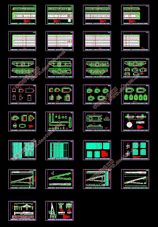
宜昌沙湾路上跨桥(2×74m独塔斜拉桥)施工图设计(含CAD图)(任务书,开题报告,论文说明书30000字,CAD图纸18张合一)
摘要
本设计的题目为宜昌沙湾路上跨桥(2×74m独塔斜拉桥)施工图设计。本设计说明书旨在对目标桥梁进行设计和分析。利用Midas Civil建模软件对目标桥梁进行成桥阶段和施工阶段分别进行模拟。在成桥阶段,查看并分析在静力荷载和移动荷载的荷载组合作用下,桥梁的变形形状以及内力图。斜拉桥在施工过程中会呈现比成桥阶段更为不稳定的状态,而且施工顺序也会对结构的位移、内力、应力等结果造成一定的影响。因此可通过其施工阶段分析来验算施工中产生的位移、内力、应力,并检查施工顺序和可施工性等方面的问题,从而找出最佳的施工顺序。对于斜拉桥,索力的调整也是一个重难点,在本说明书中也会包含索力调整过程。本设计说明书中包含桥梁的基本参数、方案比选、建模过程以及结果分析,进而完成恒载内力标准值计算、活载内力标准值计算、荷载组合、各主要构件承载力极限状态验算、各主要构件正常使用极限状态验算等。经过分析验算表明,本设计的计算方法正确,结果合理,完成设计任务的要求。
关键词:斜拉桥钢桥;成桥阶段分析;施工阶段分析;Midas Civil建模 [来源:http://www.think58.com]
Abstract
The design topic is construction drawing design of the span bridge (2×74m single-tower cable-stayed bridge) on shawan road, Yichang. This design specification aims to design and analyze the target bridge. Midas Civil modeling software was used to simulate the bridge completion stage and construction stage of the target bridge. At the bridge stage, the deformation shape and internal force diagram of the bridge under the combined action of static load and moving load are examined. In the construction stage, cable-stayed bridge will produce more unstable state than the bridge stage, and the constructionsequence will also affect the displacement, internal force, stress and other results. Therefore, the best construction order can be found by analyzing and checking the displacement, internal force, stress, construction order, constructability and other aspects generated during the construction of formfitting. For the cable-stayed bridge, the adjustment of cable force is also a difficult point, this statement will also include the adjustment process of cable force. This design manual contains basic parameters of the bridge, scheme comparison and the modeling process and the analysis of the results, and then complete the standard constant load internal force calculation, internal force values of live load calculation, loss of prestress caused by standard secondary internal force calculation, load combination, every main component bearing capacity limit state calculation and checking serviceability limit states of main components. The result shows that the calculation method is correct and the result is reasonable.
[版权所有:http://think58.com]
Key words: Cable-stayed steel bridge; Bridge stage analysis; Construction phase analysis; Midas Civil modeling
2.1设计初始资料
2.1.1技术标准
桥梁结构形式:独塔斜拉桥。
桥梁跨径:2×74m。
设计荷载:城A-荷载,双向四车道。
桥梁宽度:0.5m(防撞护栏)+0.25m(路缘带)+2×3.5m(车行道)+0.25m(路缘带)+0.5m(防撞护栏)+2.0m(锚索区)+0.5m(防撞护栏)+0.25m(路缘带)+2×3.5m(车行道)+0.25m(路缘带)+0.5m(防撞护栏)=19.0m。
桥面铺装:4cm厚SMA-13型沥青玛蹄脂混凝土(TLA+SBS复合改性)+粘层油(PC-3型乳化沥青)+ 5cmAC-16C型中粒式SBS改性沥青混凝土+防水层+ 9cmC50钢纤维混凝土
桥面横坡:双向2.0%。
桥面纵坡:3.5%。
本桥平面位于直线上。
2.1.2材料参数
钢材:主梁和桥塔均采用钢材,Q345qD。
斜拉索钢丝及锚具:主吊杆采用PES7镀锌高强钢丝,其标准强度为R=1770MPa,E=2.0×10MPa,拉索采用PES7系列冷铸墩头锚,其组合构件须符合《斜拉桥热挤聚乙烯高强钢丝拉索技术条件》(GB/T 18365-2001)要求,锚具经调制热处理,外表面镀锌。锚杯和锚圈的半成品表面在镀锌前应做磁粉探伤,磁粉探伤按JB3965规定执行。 [资料来源:http://www.THINK58.com]
混凝土:基座采用C50混凝土。
[来源:http://think58.com]
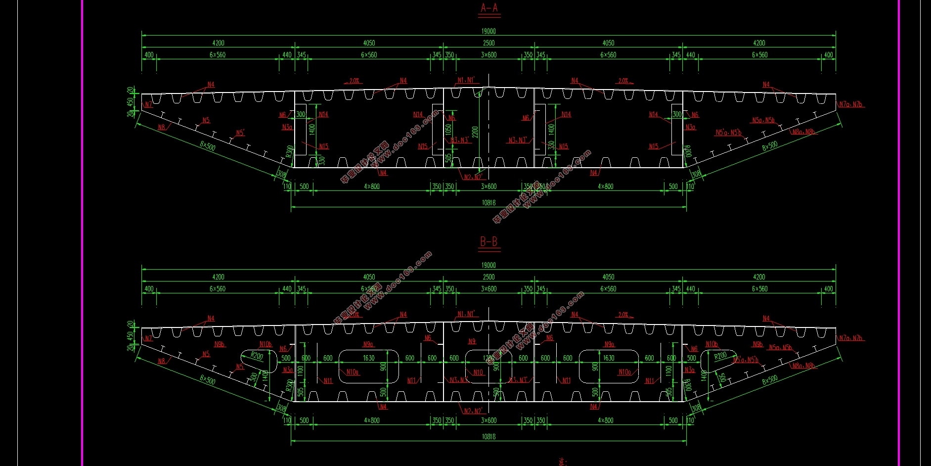
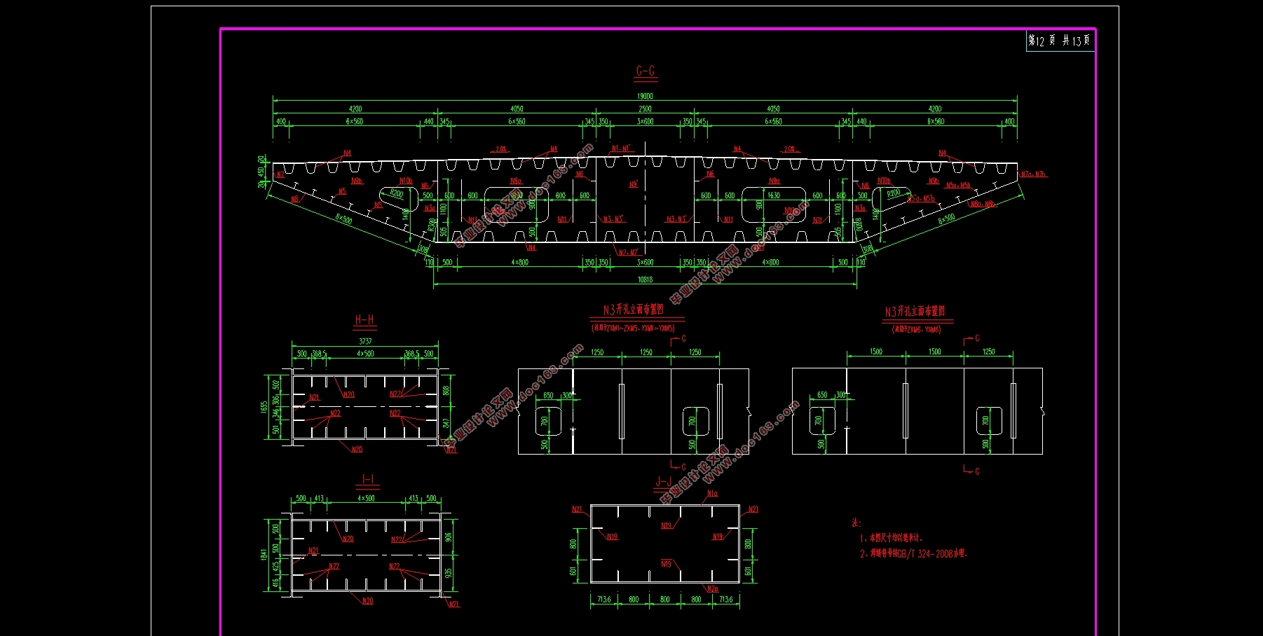
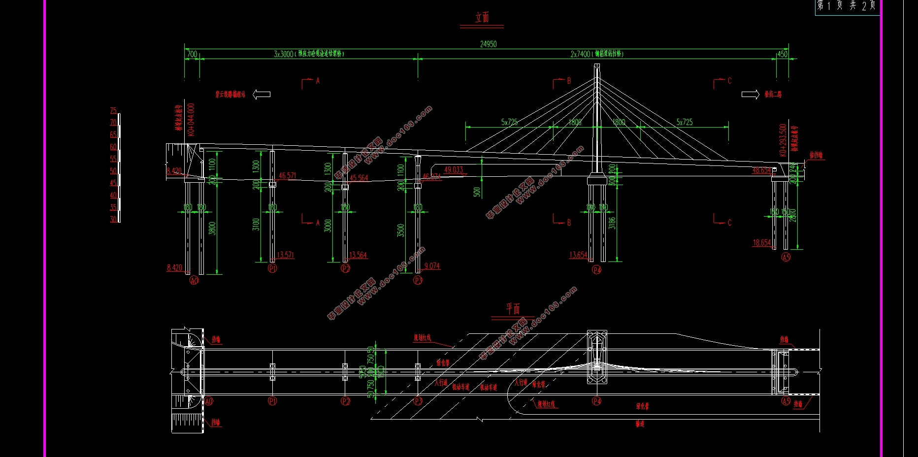
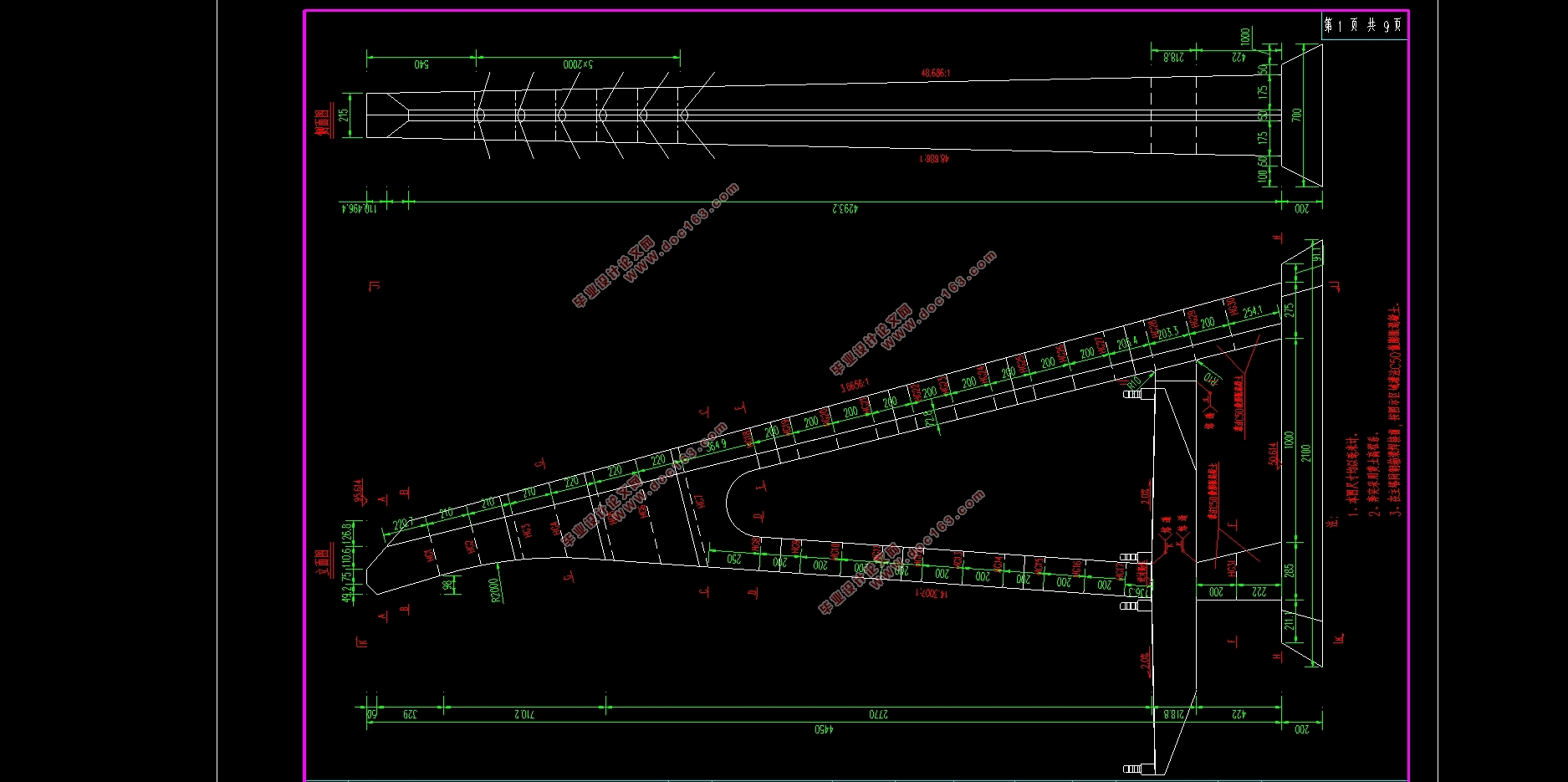
 [来源:http://www.think58.com]

目录
摘 要 Ⅰ
Abstract Ⅱ
第1章 绪论 8
1.1 课题研究的背景 8
1.2 本设计的任务要求 9
1.2.1 课题来源及背景 9
1.2.2 设计的主要内容 9
1.2.3 主要完成的任务 9
1.2.4 拟采用的技术方案及措施 9
1.3 本设计的目的及意义 10
第2章 桥梁的方案设计 11 [资料来源:www.THINK58.com]
2.1 设计初始资料 11
2.1.1 技术标准 11
2.1.2 材料参数 11
2.1.3 主要技术标准及采用规范 11
2.2 桥型比选 12
2.2.1 桥梁方案设计原则 12
2.2.2 方案比选 13
2.3 总体设计 17
2.3.1 主梁设计 18
2.3.2 桥塔设计 18
2.3.3 拉索设计 19
2.3.4 基座设计 20
第3章Midas Civil建模过程及结果分析 22
3.1 建模准备 22
3.1.1 设计建模环境 22
3.1.2 定义材料和截面特性值 22
3.2 成桥阶段建模 27
3.2.1 建立节点和单元 27
3.2.2 定义变截面组 29
3.2.3 定义边界条件 31
3.2.4 定义静力荷载工况 34
3.2.5 定义移动荷载工况 37 [资料来源:http://think58.com]
3.2.6 定义支座沉降 40
3.2.7 结构运行分析 40
3.2.8 生成荷载组合 40
3.2.9 查看分析结果 41
3.2 施工阶段建模 41
3.3.1 施工阶段模型 41
3.3.2 定义施工阶段名称 41
3.3.3 定义结构组 42
3.3.4 定义边界组 43
3.3.5 定义荷载组 43
3.3.6 定义施工阶段 44
3.3.7 施工阶段分析控制数据 46
3.3.8 结构运行分析 47
3.3.9 索力调整 47
3.3.10 查看分析结果 48
第4章 结构内力分析 49
4.1 成桥阶段分析 50
4.1.1 恒载内力分析 50
4.1.2 活载内力分析 55
4.1.3 变形形状 60
4.2 施工阶段分析 61
4.2.1 恒载内力分析 61 [版权所有:http://think58.com]
4.2.2 变形形状 66
4.2.3 索力大小 66
第5章 内力组合 68
5.1 作用组合 68
5.1.1 作用的分类 68
5.1.2 作用效应组合 68
5.2 承载能力极限状态组合 68
5.3 正常使用极限状态组合 74
第6章 施工方案 85
6.1 主梁施工 85
6.2 桥塔施工 86
6.3 拉索施工 86
6.4 基座施工 88
结论 89
参考文献 90
致 谢 92
附 录 93
上一篇:空心矩形截面桥墩承载力分析
下一篇:大沟1号桥(2×30m预应力砼先简支后连续T梁桥)左幅设计(含CAD图)
