
38+60+38mԤӦ���������������������ʩ��ͼ���(��CADͼ)
1.����ע���¼,֧��������ʾ�������ɻ�ȡ������.
2.��������ҳ���ܵ�Ϊ,���غ���ˮӡ.���Ͻ���ѧϰ�ο�֮��.
�� �� ��
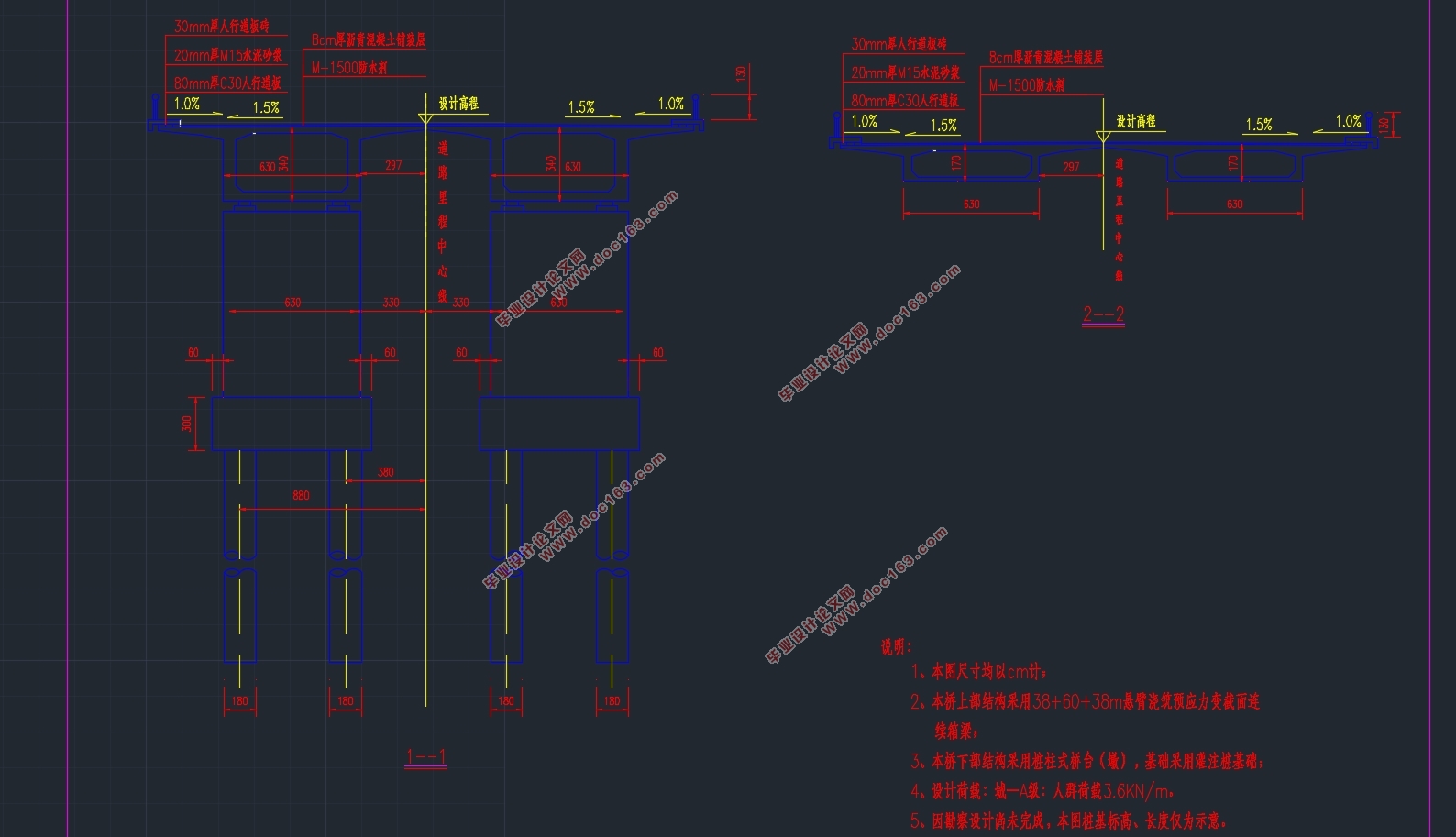
38+60+38mԤӦ���������������������ʩ��ͼ���(��CADͼ)(����˵����21000��,CADͼ20��)
ժҪ
����ҵ�����ĿΪ38+60+38mԤӦ���������������������ʩ��ͼ��ơ���羶��������Ƽ��㵱�У����е���ػ�dz��������������У�֧�����ĸ���ؿ��Զ�����е���ж�ɡ���ˣ�����ԤӦ���������������������������Ч��������ʩ�������ʱ�䣬�����˲��Ϸ�Ͷ�룬���̸���ʩ�����������㣬Ҳ�����ױ�֤������
�ڽ�����������ƹ���֮ǰ����Ҫ���������̡����������Լ��ṹ��ѧԭ���ȿ�Ŀ����һ���ۺϵĻعˡ������ܶ�������Ƶ����͵ĸ���������������ȵ�һ����ֵ��˽⡣�����ڽ����������ʱ�ܸ��ӵ����ɷ��㡣���һ���Ҫ��ϤMidas������Ӧ�ã���������ģ�ͽṹ����ȷ������
������Ƶĵ�һ��������Ϥ��ַ�ĵ��ε�ò�Լ����������Ȼ��ʼ�������͵ı�ѡ������ƴ���������ȱ���϶Լ��������ṹ�����˱Ƚϣ�����ѡ�������չ���Ϊ����Ƶ����͡�Ȼ����dz����ⶨ�����ļ��γߴ磬������Ҫ��ο��й������������ʵ�ѡ��
Ȼ�����ͨ��Midas�������������ⶨ�ijߴ磬����Խ�����һ�γ��ŵ�ģ�͡�ʩ�Ӻ��ؾ�������õ������������ԤӦ���������˹��ơ����ű�ɵ���������ƶ�����ʩ���εȣ����и��ε�������������������ѹӦ������ȡ� [������Դ��THINK58.com]
����֮�⣬����ƻ�������ԤӦ����ʧ�����������ܻ�Խṹ��������Ӱ�첢�Խ�����з����������ӳ������ؼ���������ȷ��������Ƶİ�ȫ�������ƶ������ṹ���г����塢�²��ṹ����ƽ��������㡣 ���������о����㣬������ƿ��Խ�Ϊ�۹����ļ��������������״̬�����ṩ������ؼ�����Ϣ��ָ������ʩ����
�ؼ��ʣ�Midas���������ţ������ṹ����������
Abstract
The undergraduate design of 38+60+38m Prestressed Concrete Continuous Girder Bridge with Variable Cross Section. Because the long-span bridge in the external load and under the action of the fulcrum section will appear a larger negative moment. From the absolute value of the prestressed anchor, the negative moment of the fulcrum section is greater than the positive moment of the cross section. Therefore, the use of prestressed concrete variable cross-section continuous beam, can shorten the overall duration, reduce material costs, the process is more simple, easier to operate and easier to ensure quality.
Before the bridge design work, the need for bridge engineering, basic engineering and structural mechanics and other subjects to conduct a comprehensive review. So as to be able to design the bridge of the various aspects of the force. So when we design the bridge that can be more relaxed and convenient. And we also need to be familiar with the Midas software application, which is conducive to the correct establishment of the model structure. [������Դ��THINK58.com]
The first step in the design is familiar with the topography of the bridge site and geological conditions. And then we can start to choose the bridge type of comparison. The design of the bridge from the force and the advantages and disadvantages of several bridge structures were compared. The continuous rigid bridge is the final selection of for the design of the bridge. And then we should decide the initial development of the bridge geometry, where need for more reference to the information to make the appropriate choice.
Then, we can start Midas software by using the proposed size.We can build a bridge model. The results from the model is estimated to calculate the number of .prestressed beam. And then the steel beam and mobile load construction stage can be imported in the model.Now we can start the various stages of the internal force calculation, such as the main section of the main compressive stress calculation.
In addition, the design also takes the impact of prestress loss and secondary forces on the structure into account and get the results of the analysis. The design add vehicle load and shrinkage into the model and so on to ensure the safety of bridge design. Finally, the design of the bridge deck and the lower structure is done by hand.
According to the Midas calculation results and through manual checking.The results of the analysis shows that the graduation design method is correct.The construction phase and the use of section of the internal force and stress are in line with the requirements and the design task is completed. After repeated study and calculation, this design can be more objective and fair to calculate the stress state of the bridge, and provides a lot of key information to guide the construction.
Key words: Midas; continuous rigid frame bridge; bridge structure; internal force checking
[��Դ��http://www.think58.com]


Ŀ ¼
ժҪ I
Abstract II
��1������ 1
1.1ȷ���������� 1
1.2�������� 1
1.3��ҵ��Ƶļ�ֵ 2
��2���������岼�ü��ṹ��Ҫ�ߴ� 3
2.1�ſ粼�� 3
2.2�ϲ��ṹ�ߴ��ⶨ 4
2.2.1 ��� 4
2.2.2 �����߶� 4
2.2.3 ���������� 4
2.2.4 �����װ��� 5
2.2.5 ���εĻ��� 5
2.2.6 ���������� 5
2.3�²��ṹ�ߴ��ⶨ 7
2.3.1�����ߴ� 7
2.3.2�����ߴ� 7
2.3.3��̨�ߴ� 9
2.4������ݼ��������� 10
��3�½�ģ 12
3.1ģ�ͼ� 12
3.2 3.2 ģ�͵Ľ��� 12
3.2.1 �ڶεĻ��� 12
3.2.2 ���ϲ��� 13
3.2.3 ���ز��� 14
3.2.4 ����Ķ����Լ��߽����������� 14
3.2.5 ʩ���εĶ��� 14
��4�������ṹ�������� 16
4.1�������� 16 [������Դ��http://think58.com]
4.2�������� 19
��5��ԤӦ���ֽ���Ƽ�ԤӦ����ʧ���� 22
5.1 ����ԤӦ������� 22
5.1.1 5.1.1 ����ԭ�������� 22
5.1.2 5.1.2 Midas����ԭ�� 25
5.1.3 5.1.3 ������������Ա� 26
5.1.4ԤӦ����IJ��� 27
5.2 ԤӦ����ʧ����ЧԤӦ������ 28
5.2.1 ԤӦ������ܵ�֮���Ħ�������ԤӦ����ʧ 28
5.2.2ê�߱��Ρ��ֽ�����ͽӷ�ѹ�������Ӧ����ʧ 29
5.2.3 ԤӦ���ֽ���̨��֮����²��������ʧ 29
5.2.4 ����ѹ����ʧ 30
5.2.5 �ֽ��ɳ������Ӧ����ʧ 30
5.2.6 ��������������������ԤӦ����ʧ 31
5.2.7 ԤӦ����ʧ������ 31
��6�´��������㼰������� 37
6.1�¶ȴ����� 37
6.1.1�������ݼ����� 37
6.1.2�¶ȴ����������� 38 [������Դ��www.THINK58.com]
6.2���������ȳ��������� 42
6.3ԤӦ�������� 44
6.4���������� 46
6.5�������� 48
6.6������� 50
6.6.1������������״̬��� 50
6.6.2����ʹ�ü���״̬��� 52
��7����Ҫ�������� 55
7.1������������״̬�������� 55
7.1.1 �������� 55
7.1.1������ 56
7.1.1ʹ�ý�б���濹������ 58
7.1.2б���濹������ 61
7.2����ʹ�ü���״̬�������� 62
7.2.1ʹ�ý������濹������ 62
7.2.2�Ӷ����� 65
7.3�־�״���Ͷ���״��������Ӧ������ 65
7.3.1ʹ�ý�������ѹӦ������ 65
7.3.2ʹ�ý�б������ѹӦ������ 67
7.3.3ʩ���������淨��Ӧ������ 70
7.3.4�������ֽ����Ӧ������ 73 [��Ȩ���У�http://think58.com]
��8���������� 76
8.1�м䵥������ 76
8.1.1�������� 76
8.1.2�������� 76
8.1.3������� 77
8.2��������۰��������� 78
8.2.1�������� 78
8.2.2�������� 78
8.2.3������� 79
8.3������ 79
8.3.1֧�㴦��� 80
8.3.2������� 80
��9���²��ṹ���� 82
9.1�Ŷռ��� 82
9.1.1�������� 82
9.1.2������� 82
9.1.3������� 83
9.2���ע���� 84
9.2.1�����ٶ� 84
9.2.2�������ⶨ 84
9.2.3������������ 84
9.2.4������������ 90
9.2.5�������� 90
����� 93
[������Դ��THINK58.com]
��л 94
��һƪ����·��������ԤӦ�������������������(48m+80m+48m)(��CADͼ)
��һƪ��35+50+35mԤӦ����������������ʩ��ͼ���(��CADͼ)