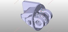
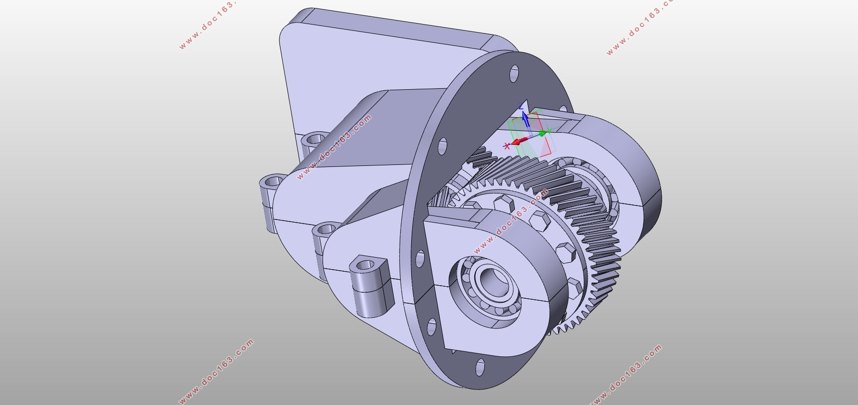
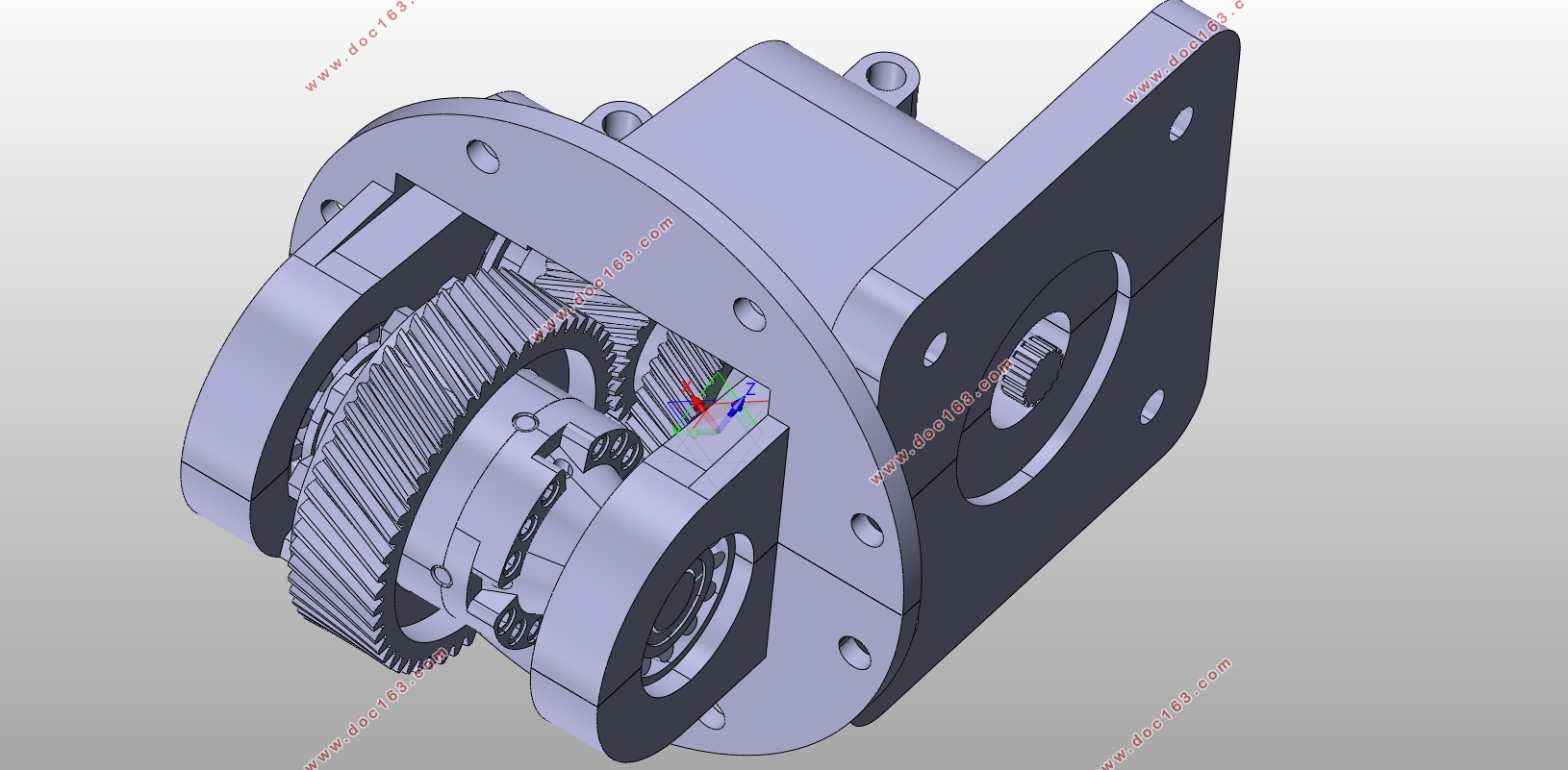
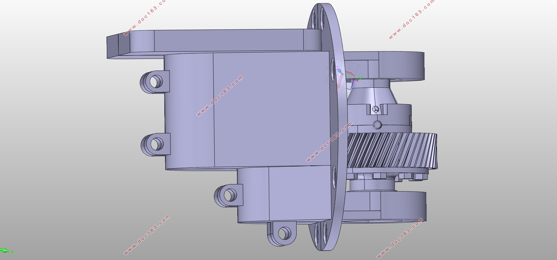
电驱动系统减速器虚拟设计(含CAD零件图装配图,CATIA三维图)
1.无需注册登录,支付后按照提示操作即可获取该资料.
2.资料以网页介绍的为准,下载后不会有水印.资料仅供学习参考之用.
密 惠 保
电驱动系统减速器虚拟设计(含CAD零件图装配图,CATIA三维图)(任务书,开题报告,文献摘要,外文翻译,论文说明书13000字,CAD图5张,CATIA三维图)
摘要
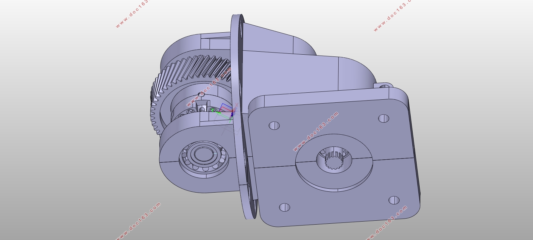
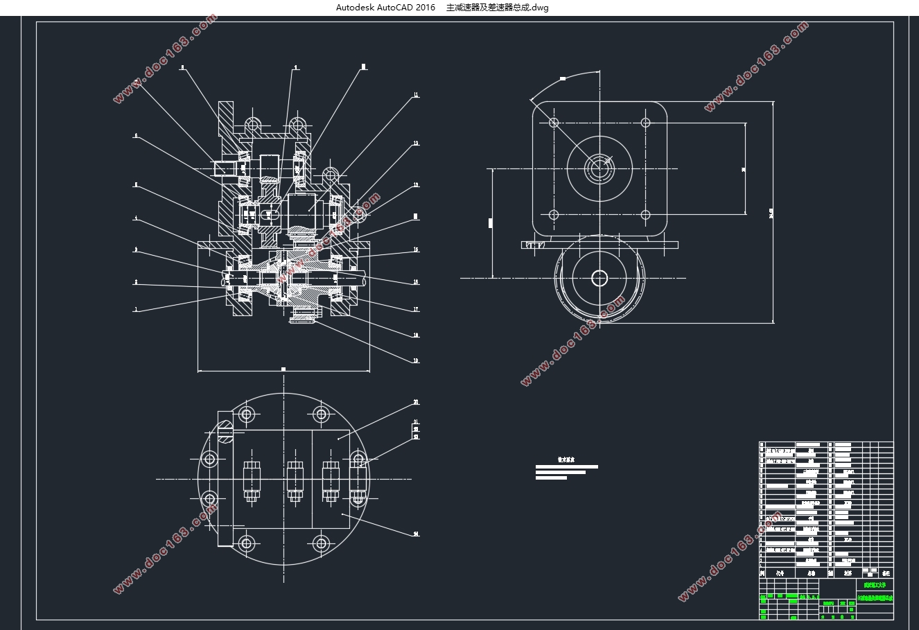
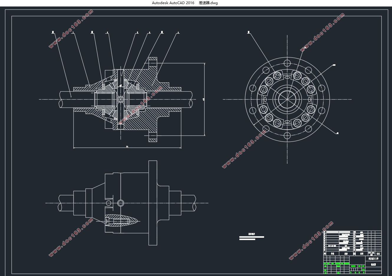
在纯电动汽车中,电驱动系统是最主要、最核心、最复杂的部件,对车辆的运行性能有重要影响。本文针对一款地下电动工程车,根据工作环境的特点,为其设计出一款合适的减速器。在综合考虑后,确定工程车的电驱动系统采用电动机—驱动桥组合驱动形式。减速器选用双级斜齿圆柱齿轮式主减速器。本文首先计算得到电动机的参数,由此对主减速器、差速器进行了方案设计和参数计算。在得到所需参数后,运用CATIA三维软件对主减速器及差速器总成进行三维建模。最后使用ANSYS有限元分析软件进行强度分析,来验证设计的可靠性。结果证明,设计出的主减速器及差速器总成符合设计要求。
关键词:电驱动系统;主减速器;差速器;三维建模;有限元分析
Abstract
The electric drive system is the most important, the core, the most complex components of pure electric vehicles which has an important impact in the performance of the vehicle. According to the characteristics of the working environment, this paper designs a suitable reducer forthe vehicle. After the comprehensive consideration, choosinga combination drive form with motor and drive axle as the electric drive system of the engineering vehicle. Theselection of reducer isdouble helical cylindrical gear final drive. This paperfirst calculated the parameters of the motor, then do the design and parameter calculation for final drive and differential. After obtaining the required parameters, three-dimensional modeling of the final drive and differential assembly is establishedby using 3D software CATIA. Finally, using finite element analysis software ANSYS for strength analysis, to verify the reliability of the design. The results show that the design of the final drive and differential assembly satisfies the design requirements.
[资料来源:www.THINK58.com]
Key Words:electric drive system;final drive;diffrential;3D modeling;FEA
动力参数的确定
2.1整车基本参数
地下电动工程车在狭小的地下管网系统中工作,由于空间的限制,整车尺寸小,为2.3m×1.3m×1.8m。单车的整备质量不超过650kg,该车要求能在车上坐满四人(每人75kg),装载550kg货物的情况下再拉动一辆相同的工程车。因此,工程车行驶时最大总质量为2150kg。要求的最高行驶车速为15km/h,最低车速为5km/h。能实现双向行驶。受限于尺寸,本文选择固定速比减速器,不采用变速器,只使用主减速器来实现减速增扭。
电机基本参数表
电机名称 永磁同步电机
额定功率 4.5kw
峰值功率 9.0kw
峰值扭矩 65N•m
额定/最高转速 3000/5500rpm
外形尺寸 162mm×162mm×242mm
[资料来源:www.THINK58.com]

目录
第1章绪论 1
1.1 课题研究的目的和意义 1
1.2 国内外研究现状 1
1.3 本文的研究内容 3
1.4 论文结构 3
第2章动力参数的确定 4
[来源:http://think58.com]
2.1整车基本参数 4
2.2 电动机功率的确定 4
2.3 传动比i的确定 5
第3章主减速器设计 7
3.1 主减速器齿轮设计 7
3.1.1 齿轮类型选择 7
3.1.2 齿轮材料选择 7
3.1.3 齿轮基本参数的计算 8
3.2 主减速器齿轮轴设计 10
3.2.1 轴结构设计 10
3.2.2 轴的材料选择 12
3.3 主减速器轴承选型 13
第4章差速器设计 14
4.1 差速器的类型 14
4.2 差速器的工作原理 14
4.3 差速器的齿轮设计 15
4.3.1齿轮基本参数的计算 15
4.3.2差速器齿轮强度计算 17
4.4 差速器零件的三维模型 18
第5章基于Ansys的零件有限元分析 19
5.1零件有限元分析 19
5.2.1一级减速齿轮有限元分析 19 [资料来源:www.THINK58.com]
5.2.2 二级减速齿轮有限元分析 20
5.3结果分析 20
第6章结论与展望 21
6.1结论 21
6.2展望 21
参考文献 22
致谢 23 [来源:http://www.think58.com]
