
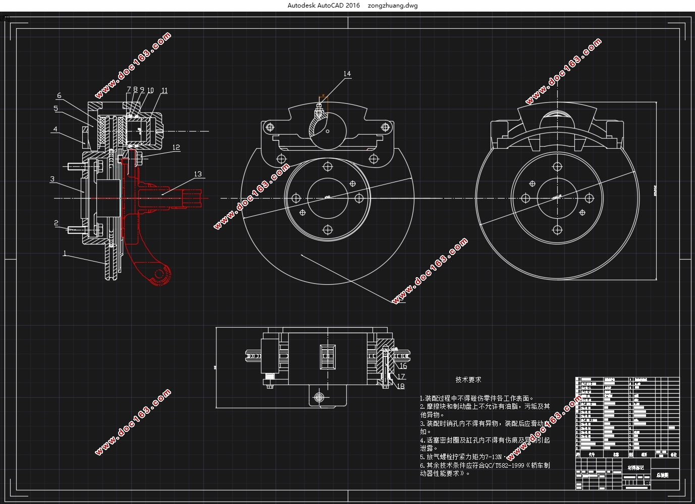
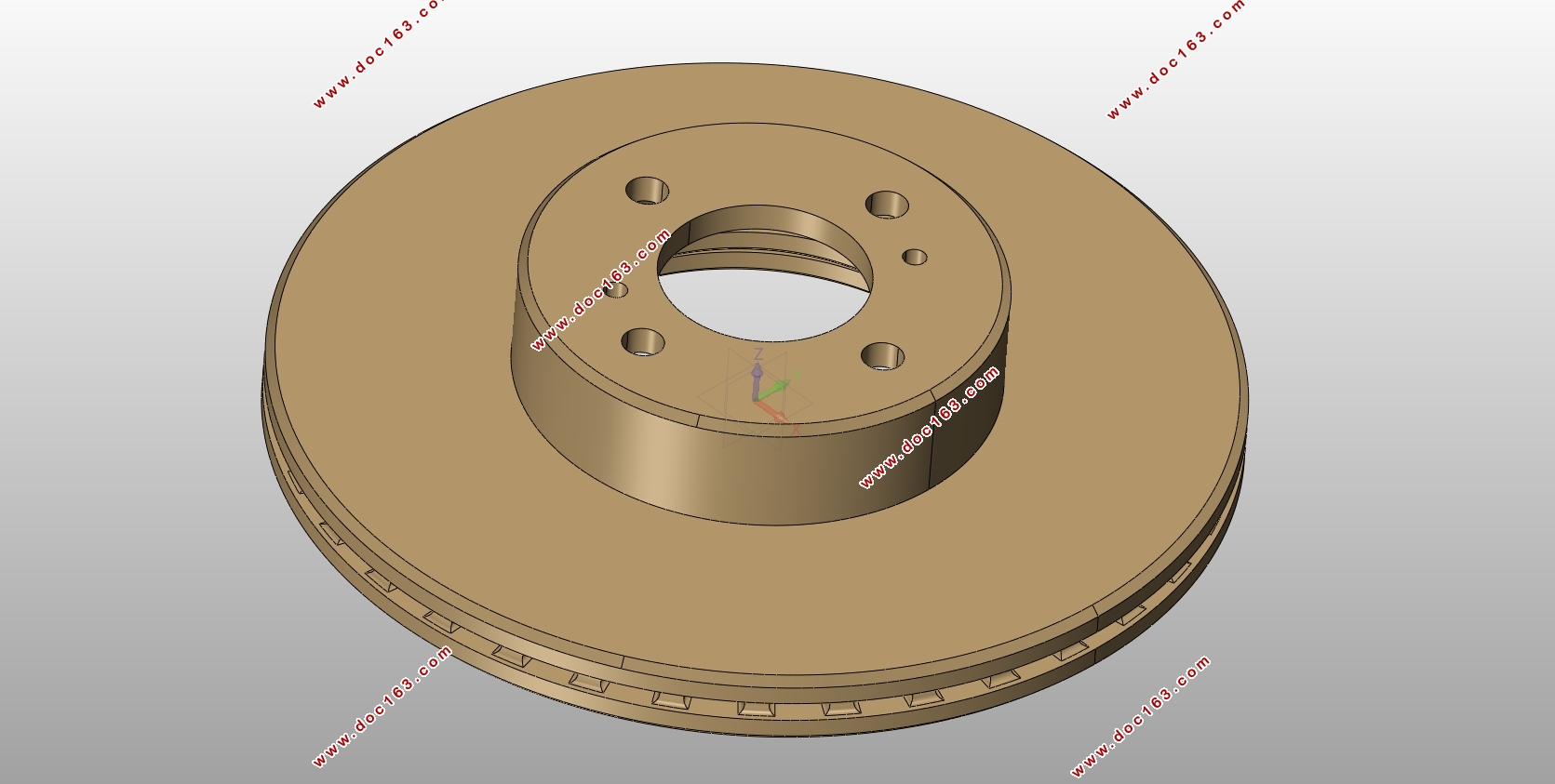
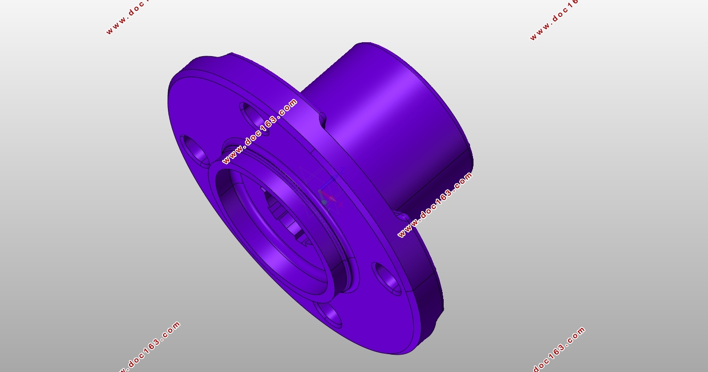
奥迪轿车制动系统设计(含CAD零件图装配图,CATIA三维零件图)
1.无需注册登录,支付后按照提示操作即可获取该资料.
2.资料以网页介绍的为准,下载后不会有水印.资料仅供学习参考之用.
密 惠 保
奥迪轿车制动系统设计(含CAD零件图装配图,CATIA三维零件图)(任务书,开题报告,论文说明书8000字,CAD图6张,CATIA三维零件图)
摘要
制动系统是汽车系统的关键一环,设计它的目的是制约汽车的运动状况,以保证汽车的安全。本论文主要阐述了奥迪轿车制动系统的设计过程,包含主要部件的结构选择等。本论文主要采用文献分析法,查阅资料,了解制动系统原理以及一般设计过程,再结合参考车型,着手设计计算并进行校核,使之符合设计要求以及国家规定的轿车相关性能安全要求。最终在自己查阅大量资料,学习三维绘图软件,向同学请教,以及老师的耐心指导下,完成了课题设计,设计出一款适用于奥迪轿车的制动系,对于制动系统的发展现状,研究方法以及前景有了一定的了解,对所学知识进行了巩固和提升。
关键词:盘式制动器,设计,制动系统
Abstract
Braking system is an important part of the car, the purpose of its design is to restrict the movement of the car in that the safety of the car can be ensured. The main contents of this thesis are to elaborate the design process of the Audi car brake system, including the selection of the brake, the selection of the main parameters of the brake system, the structural selection of the main components, the design calculation and the checking and braking performance analysis. This paper mainly uses the literature analysis method by accessing to the information to understand the principle of the brake system and the general design process. Combined with reference models, we do the design calculation and verification to meet the design requirements and the provisions of the national car safety performance requirements. And finally in my own access to a large number of information, learning three-dimensional drawing software, as well as the teacher's careful guidance and the enthusiastic help of students, I completed the design, design a suitable for the Audi car brake system, the development of the braking system. I have a certain understanding of the development of the braking system, research methods and prospects, and the knowledge I have learnt has been consolidated and enhanced.
Key Words:structural,check calculation
制动系的主要参数及选择
相关参数确定
表3-1
编号 名称 符号 数值 单位 备注
1 轴距 L 2908 mm
2 前后轮距 1566,1549 mm
3 质量 m 1565/1930 kg 空载和满载
4 质心高度 hg 520/510 mm 空载和满载
5 质心距前轴 a 1425 mm
6 质心距后轴 b 1483 mm
7 前轴负荷 F_Z1 12299 N 65%
8 后轴负荷 F_Z2 6615 N 35%
9 轮胎规格 205/60R15
同步附着系数
同步附着系数φ_0的选择与很多条件都有关联。我们先看汽车制动时的几种状况。
当路面的附着系数φ不同时制动,有如下可能:(1)φ<φ_0时,β线在I线下方,一定为前轮先抱死拖滑,前轮不再具备转向能力。(2)φ>φ_0, β线在I线上方,一定为后轮先抱死,后轴很可能会产生侧滑,从而使汽车方向不稳,甚至产生漂移。
[资料来源:http://THINK58.com]

[资料来源:THINK58.com]
目录
第1章 绪论 6
1.1. 制动系统的基本概念 6
1.2. 制动系统的现状 6
1.3. 课题主要内容 6
1.4. 研究方案 6
第2章 制动系统工作原理及结构形式的选择 3
2.1. 工作原理 3
2.2. 鼓式制动器的结构形式 3
2.3. 盘式制动器 3
2.4. 本次设计的选型及原因 4
第3章 制动系的主要参数及选择 5
3.1. 相关参数确定 5
3.2. 同步附着系数 5
3.3. 制动力分配系数 5
3.4. 制动器制动力矩 6
3.5. 制动效能 6 [资料来源:http://think58.com]
3.6. 盘式制动器主要参数确定 6
3.6.1. 制动盘直径D 6
3.6.2. 制动盘厚度h 7
3.6.3. 摩擦衬块内外半径R1 ,R2 7
3.6.4. 摩擦衬块工作面积A 7
第4章 制动器的设计计算及校核 9
4.1. 摩擦衬块磨损特性计算 9
4.1.1. 比能量耗散率 9
4.1.2. 比滑磨功 9
4.2. 制动器的热容量和温升校核 10
4.3. 盘式制动器制动力矩计算 10
4.4. 驻车制动计算和校核 11
第5章 制动器主要零部件结构设计与计算 13
5.1. 制动盘 13
5.2. 制动块 13
5.3. 制动钳 13
5.4. 制动轮缸 14
5.5. 摩擦材料 14
5.6. 制动器间隙的自动调整装置 14
第6章 制动驱动机构 15
6.1. 制动驱动机构的形式 15
6.2. 分路系统的选择 15
6.3. 液压制动驱动机构设计 16
6.3.1. 制动轮缸直径与工作容积 16
6.3.2. 制动主缸直径与工作容积 17
6.3.3. 制动踏板力与踏板行程 18
第7章 制动性能分析 19
7.1. 制动性能评价指标 19
第8章 结论 21 [资料来源:THINK58.com]
上一篇:东风雪铁龙爱丽舍后悬架设计(含CAD零件装配图,CATIA三维图)
下一篇:汽车CAD系统―驱动桥计算校核模块(含CAD图,VB程序)