
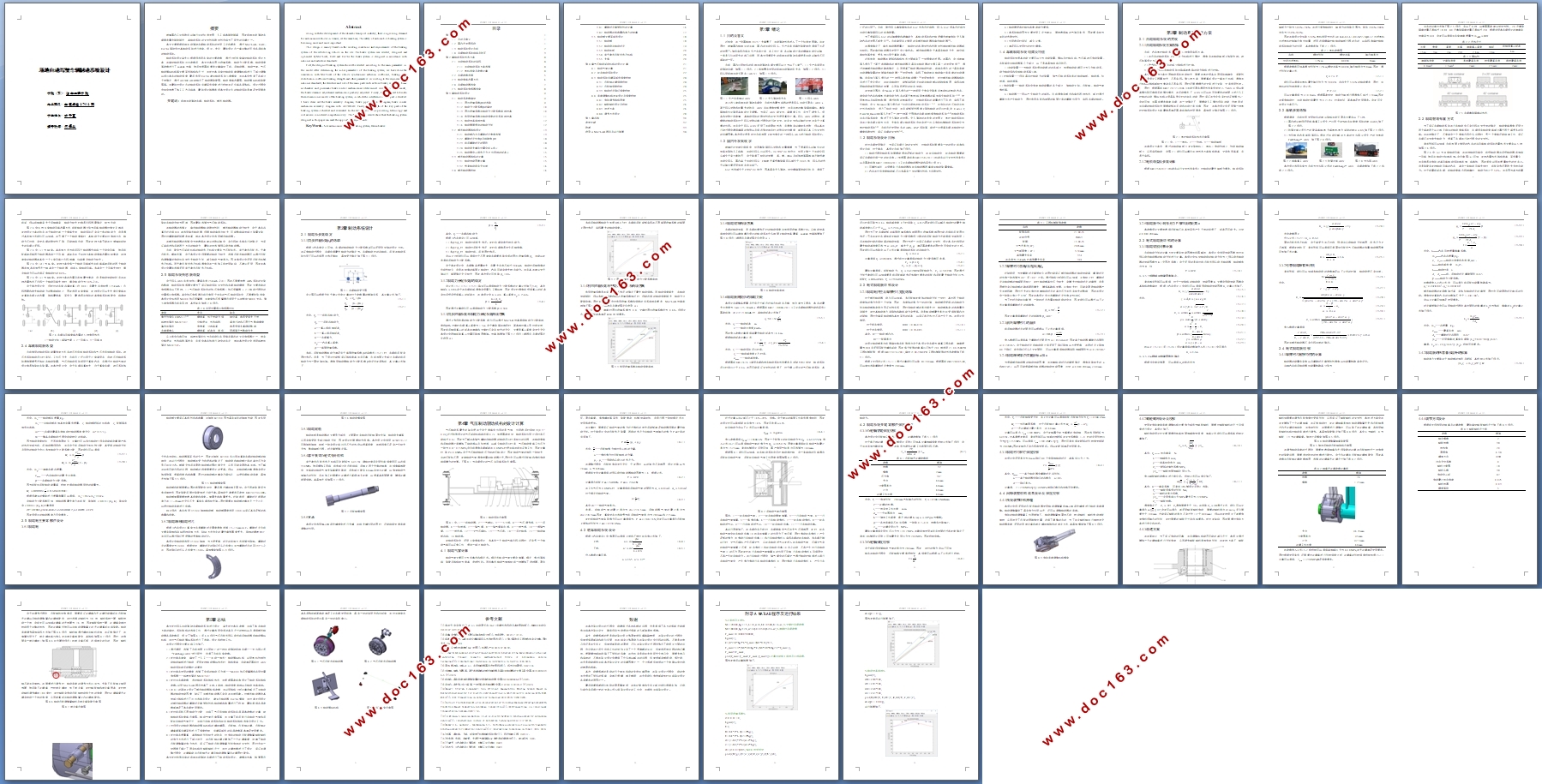
场地自动驾驶车辆制动系统设计(含CAD零件图装配图,STP三维图)
1.无需注册登录,支付后按照提示操作即可获取该资料.
2.资料以网页介绍的为准,下载后不会有水印.资料仅供学习参考之用.
密 惠 保
场地自动驾驶车辆制动系统设计(含CAD零件图装配图,STP三维图)(任务书,开题报告,论文说明书17500字,CAD图8张,STP三维图)
摘要
随着国内工业和物流运输行业的快速发展,人工成本越来越高,因此场地自动驾驶车辆需求量也越来越大,其制动系统的安全性和稳定性也成为了研究的关键之一。
本文主要根据场地自动驾驶车辆制动系统的使用工况和要求,通过MATLAB、CAD、CATIA等软件对其制动系统进行选型、设计、优化,最终设计出一套完整的符合各项标准的制动系统。
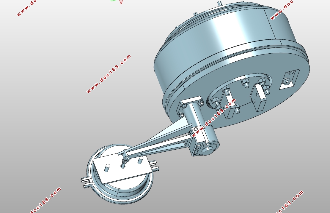
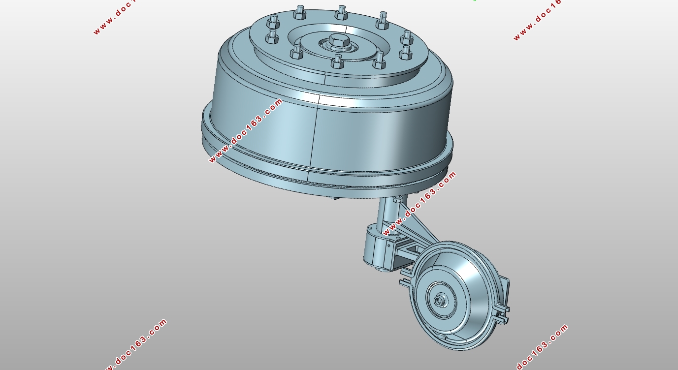
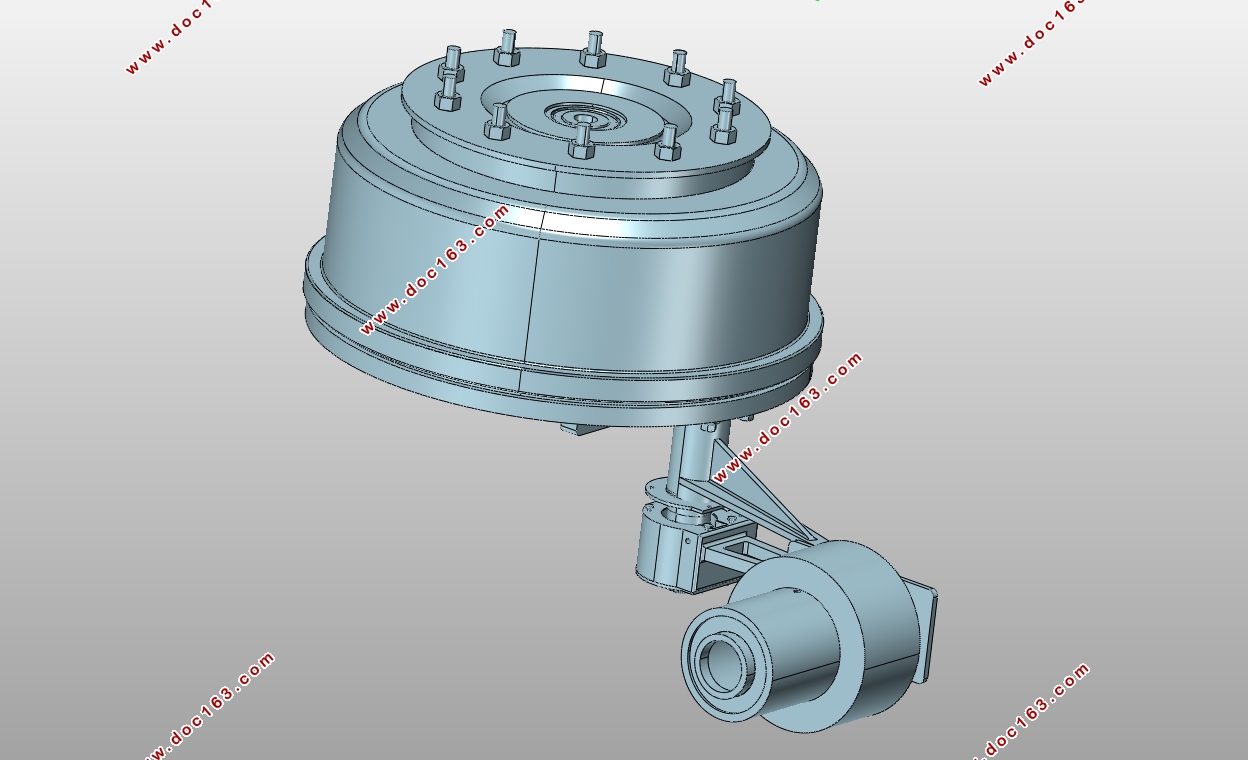
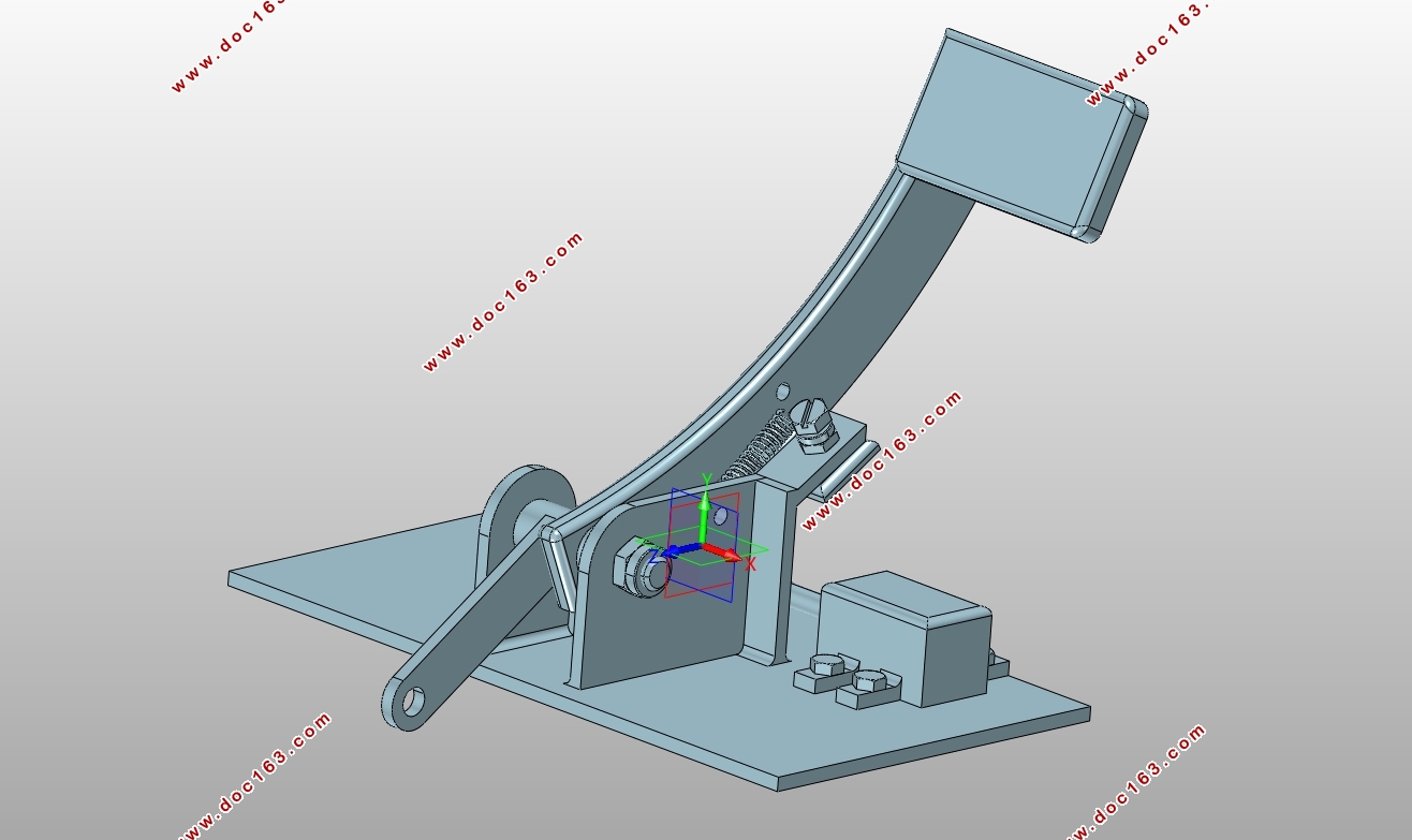
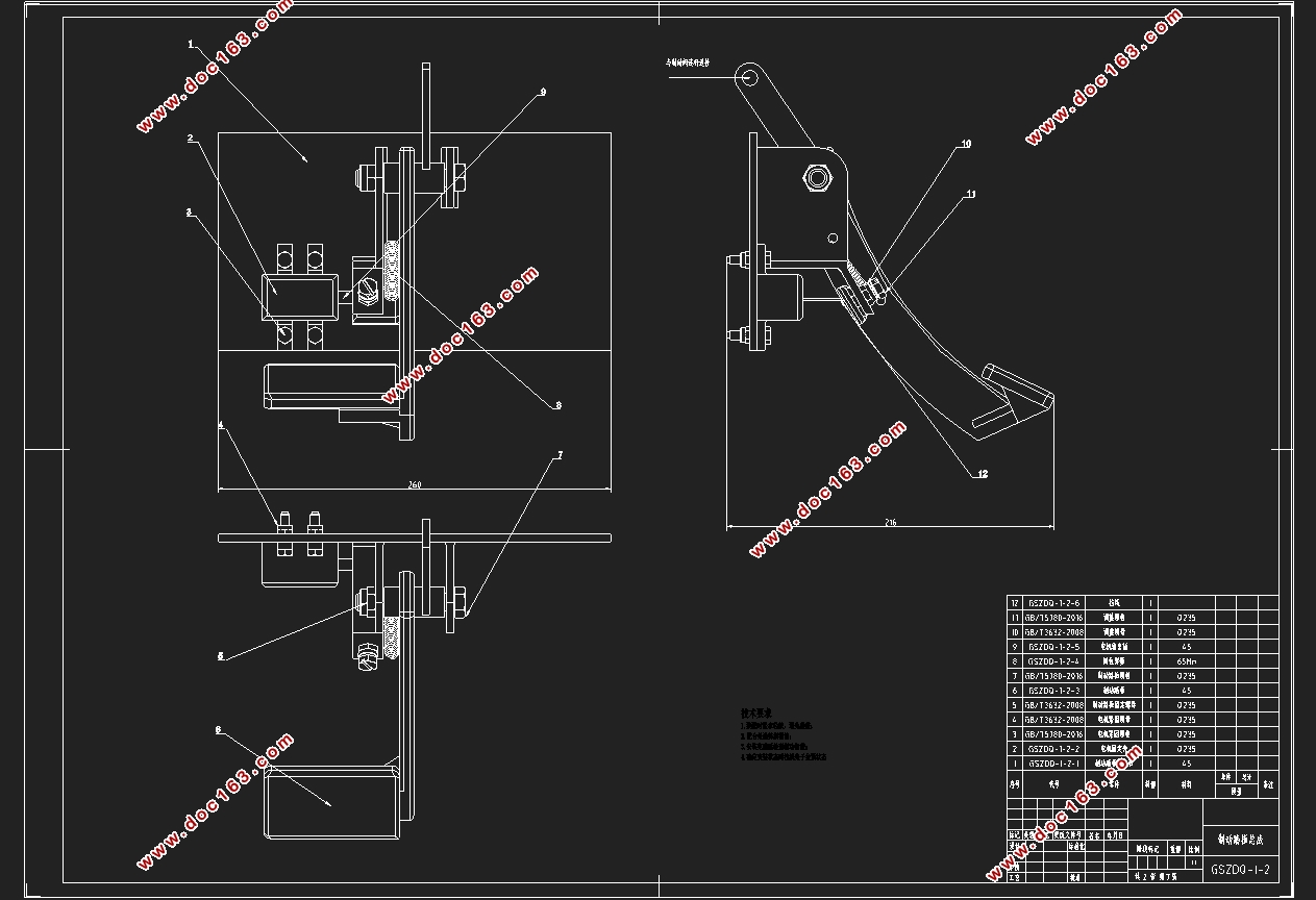
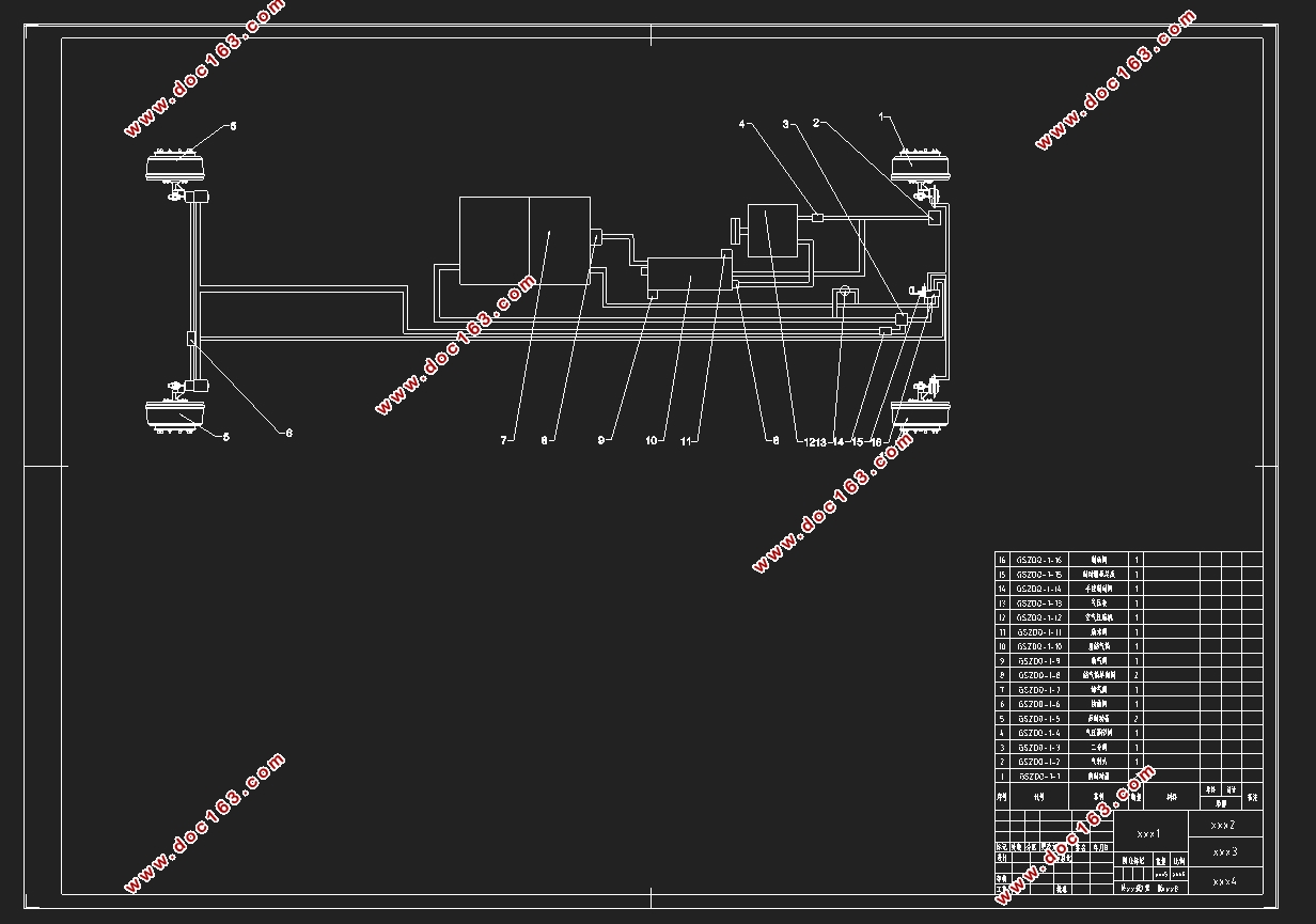
制动系统设计首先应根据所选用车型的主要参数,通过分析选型确定制动系统设计方案,在确定制动系统初步参数后,本文对本车同步附着系数、制动力分配系数、制动强度等参数进行了matlab仿真,然后按照国标要求计算确定了前、后制动器、制动气室、气压制动操纵机构等主要零件结构和尺寸,并针对本车型对制动间隙调整机构进行了部分调整,以适应本车的制动强度,最后利用CATIA建立制动系统三维模型,并在其中检查了各部分干涉情况,通过AUTOCAD绘制出了制动器装配图、制动管路布置图、制动操纵机构装配图等。并最终对设计出的制动系统关键零件强度进行校核并评价其各项指标。设计过程中也综合考虑了加工工艺及成本,最终设计结果表明本文设计出的制动系统是满足使用需求的。
关键词:场地自动驾驶车辆;制动系统;鼓式制动器。
Abstract
Along with the development of the domestic transport industry, there is a growing demand for autonomous vehicles in venues, At the same time, The safety of automobile braking system is becoming more and more important.
This design is mainly based on the working conditions and requirements of the braking system of the self-driving vehicle on the site. The brake system was selected, designed and optimized byMATLAB, CAD and CATIA.The brake system is designed in accordance with national and industrial standards.
First,the design of braking system should be selected according to the main parameters in the model.After determining the initial parameters of the braking system, we have done the simulation with MATLAB of the vehicle synchronous adhesion coefficient, braking force distribution coefficient braking strength and other parameters. According to the requirements of national standards, the structure and size of the main parts such as front brake, rear brake, brake air chamber and pneumatic brake control mechanism are determined. According to this model, the brake clearance adjustment mechanism is partially adjusted. Finally, CATIA is used to build a three-dimensional model of the braking system, in which the interference of each part is checked. I have draw out the brake assembly diagram, brake pipeline layout diagram, brake control mechanism assembly diagram with AUTOCAD. Finally, the strength of the key parts of the braking system is checked and evaluated. In the design process, the processing technology and cost are also considered comprehensively. The final design results show that the braking system designed in this paper can meet the application requirements.
.Key Words:Site autonomous vehicles; Braking system; Drum brakes.
[资料来源:www.THINK58.com]
 [资料来源:THINK58.com]
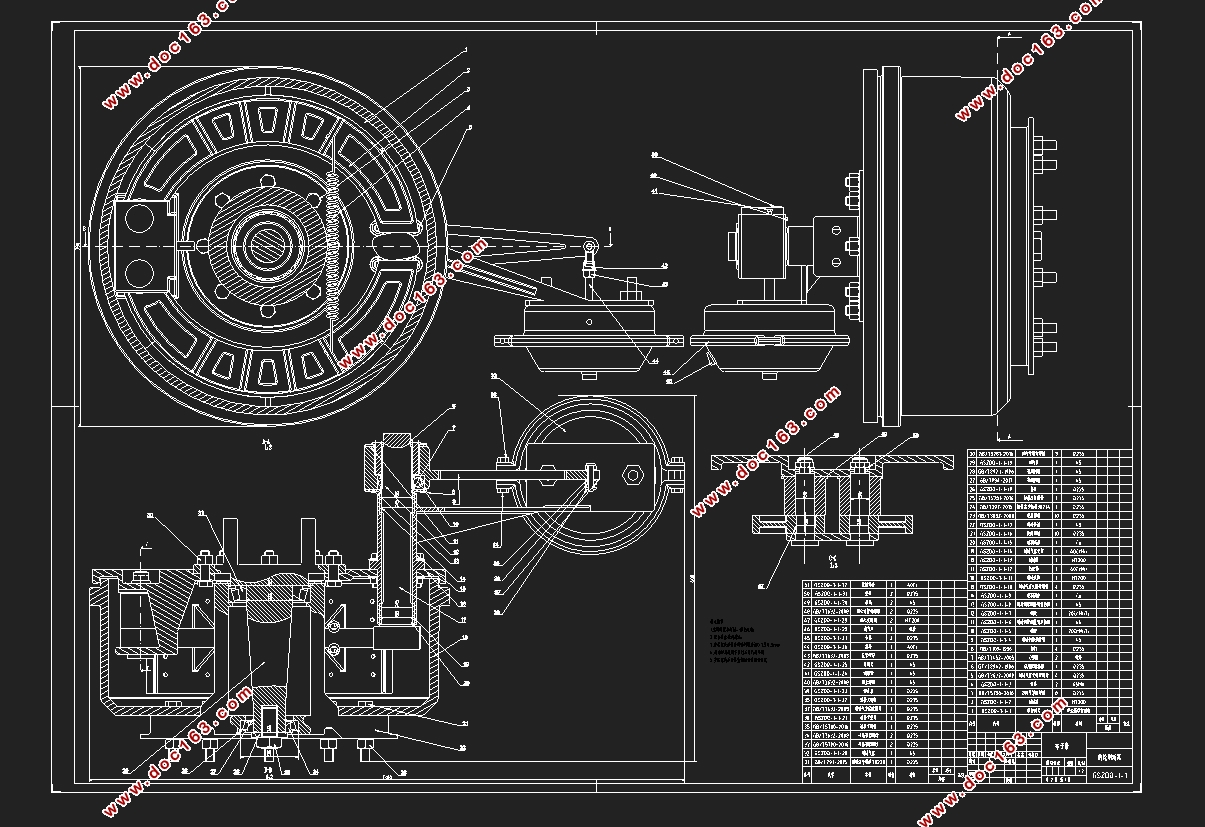

[版权所有:http://think58.com]
目录
第1章绪论 1
1.1 目的及意义 1
1.2 国内外发展现状 1
1.3 制动系统设计目标 2
1.4 车辆制动系统组成及特征 3
第2章制动系统技术方案 4
2.1 自动制动系统的实现 4
2.1.1 自动制动系统方案选择 4
2.1.2 电机选型及参数计算 4
2.2 车辆参数选择 5
2.3 制动管路布置方式 6
2.4 车辆制动器选型 7
2.5 制动系统传感器选型 8
第3章制动系统设计 9
3.1 制动系参数确定 9
3.1.1 同步附着系数ϕ0的选取 9
3.1.2 制动力分配系数β的确定 10
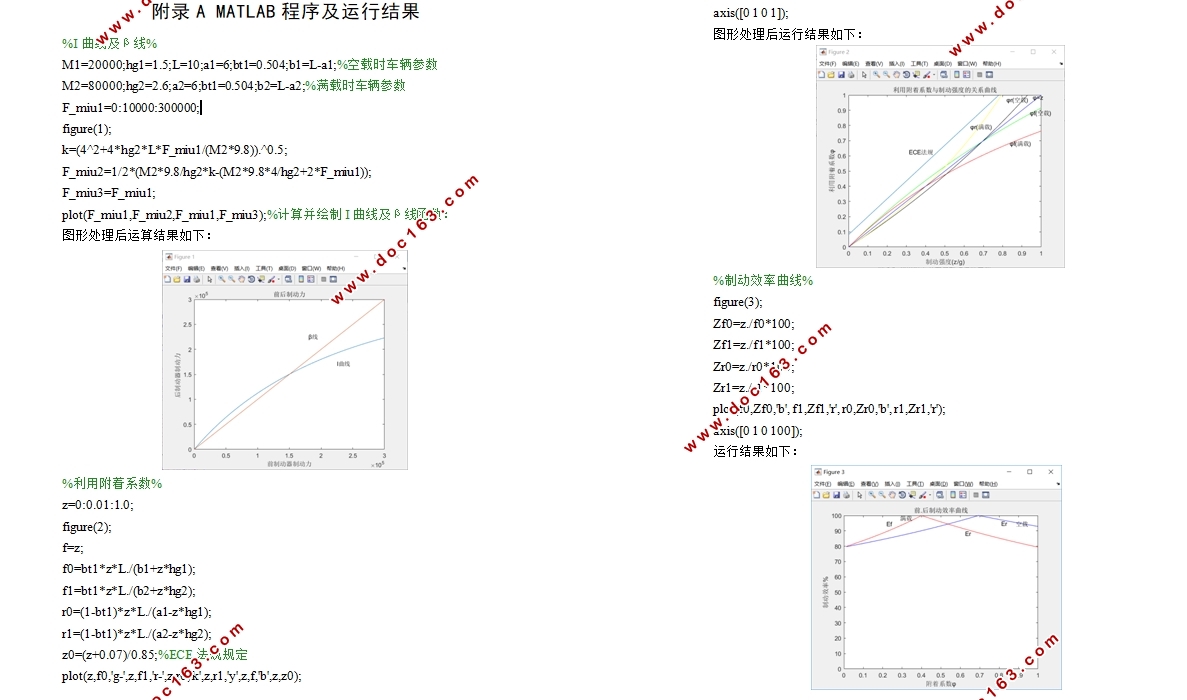
3.1.3 同步附着系数与制动力分配系数曲线仿真 10
3.1.4 利用附着系数与制动强度的关系曲线仿真 11
3.1.5 制动效率曲线仿真 12 [来源:http://think58.com]
3.1.6 制动器需提供的制动力矩 12
3.2 鼓式制动器结构设计 13
3.2.1 制动鼓内径及摩擦衬片宽度选择 13
3.2.2 摩擦衬片包角β及起始角β0 14
3.2.3 前后摩擦衬片的面积 14
3.2.4 制动蹄支撑点位置坐标a和c 14
3.2.5 制动器中心到张开力P作用线的距离e 15
3.3 鼓式制动器结构的计算 15
3.3.1 制动效能因素计算 15
3.3.2 检查制动蹄有无自锁 16
3.4 鼓式制动器校核 16
3.4.1 摩擦衬片磨损特性的计算 16
3.4.2 制动器的热容量和温升的核算 17
3.5 制动鼓主要零部件设计 18
3.5.1 制动鼓 18
3.5.2 制动蹄与制动衬片 19
3.5.3 制动底板 20
3.5.4 非平衡式凸轮式张开机构 20
3.5.5 支承 20
第4章气压制动驱动机构的设计计算 21
[资料来源:http://www.THINK58.com]
4.1 制动气室计算 21
4.2 驻车制动系统设计 22
4.3 制动系统关键零部件强度校核 24
4.3.1 凸轮轴花键强度校核 24
4.3.2 凸轮轴强度校核 24
4.3.3 制动衬片铆钉强度校核 25
4.4 间隙调整机构改良设计及强度校核 25
4.4.1 传统调节结构原理 25
4.4.2 蜗轮蜗杆设计及校核 26
4.4.3 改进方案 26
4.4.4 调节方式设计 28
第5章总结 30
参考文献 32
致谢 33
附录A MATLAB程序 [资料来源:http://think58.com]
上一篇:小型纯电动代步汽车总体设计(含CAD零件图装配图,STP,CATIA三维图)
下一篇:1.5T汽油机曲轴设计与开发(含CAD零件图,SolidWorks三维零件图)