轿房车线控转向系统设计(含CAD零件图装配图)

1.无需注册登录,支付后按照提示操作即可获取该资料.
2.资料以网页介绍的为准,下载后不会有水印.资料仅供学习参考之用.
密 惠 保
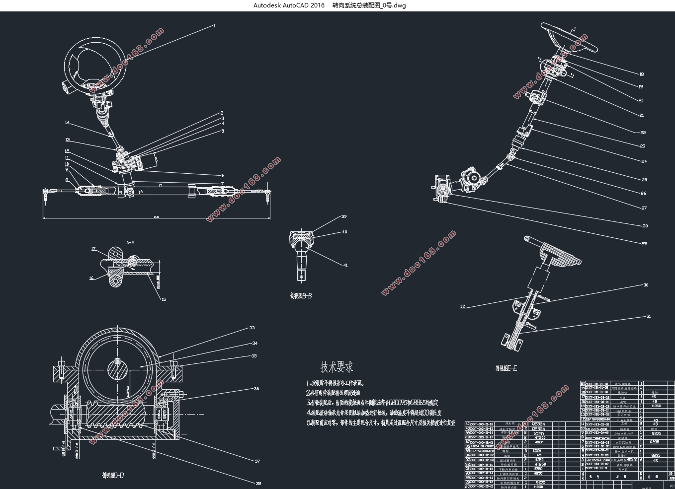
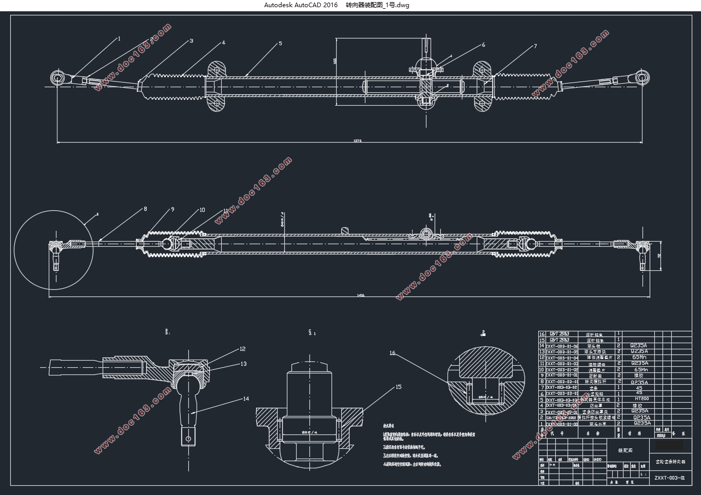
轿房车线控转向系统设计(含CAD零件图装配图)(任务书,开题报告,论文说明书25000字,CAD图7张)
摘 要
线控转向系统由于取消了方向盘与转向轮之间的机械连接,主要是由传感器、控制器、执行器来完成转向任务,系统可分为转向执行模块、控制器模块、方向盘模块以及辅助的冗余模块组成。本文基于这四个模块对汽车的线控转向系统展开了设计与仿真。
首先,通过对线控转向系统执行模块的硬件组成分析,并根据硬件的工作要求以及性能对各硬件进行了选型与计算;由于转向执行电机是线控转向系统的动力源,它为车辆转向提供转向力矩,根据对转向执行电机特性的分析,选择永磁有刷直流电机作为执行电机,基于此建立电机动力学模型,将转向执行电机转矩的电压控制及电流闭环控制分别在Matlab/Simulink作了仿真分析,结果表明电流闭环控制是可以更好地实现对目标电流的控制,从而满足转向执行电机的控制要求。然后建立外环以转角控制的2环串级PID仿真模型,同电机动力学模型一起建立汽车线控转向系统模型并在Simulink中进行仿真分析。通过与传统的转向系统的质心侧偏角与横摆角速度响应的进行比较,不仅验证了模型同时也说明转向执行电机的电流闭环控制策略是合理的。 [资料来源:http://think58.com]
其次,对冗余系统进行了设计,根据对目前三种常见的冗余设计比较,本文采用线控转向系统和电动助力系统的冗余设计方案,既可提高性能又可降低成本。接着对系统的方向盘模块进行了分析,通过对这个模块的硬件组成分析,根据其要求对主要硬件进行选型与计算;其中路感电机总成采用的与执行模块相同。然后对传统汽车转向时路感来源进行分析,并对方向盘总成进行动力学建模,建立以车速和方向盘转角为变量的路感算法,并利用Matlab/Simulink软件进行了仿真验证。仿真分析结果表明利用该算法得到的回正力矩可较好地模拟汽车的路感特性,同时可以将得到的回正力矩作为路感控制系统的目标转矩,也就是作为控制系统的目标电流,然后对路感电机进行控制策略分析。
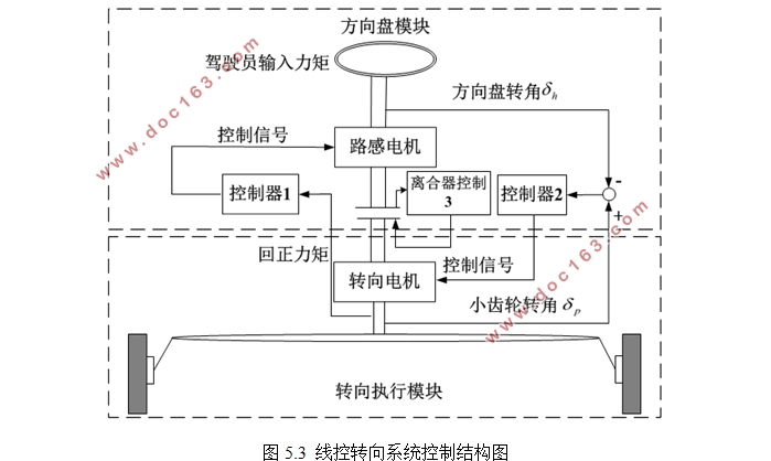
最后,对控制器模块进行了理论结构分析,经过对执行模块和方向盘模块的分析,本文采用2通道的线控转向控制结构,其前向通道和反馈通道分别只有转角或力矩单一的信息,但其优点是控制结构简单,并且稳定性相对多通道控制结构较好,前向通道为将小齿轮转角信号与方向盘转角的差值作为控制信号控制转向电机,实现汽车转向控制;反馈通道为由转向回正力矩作为控制依据控制路感电机,实现驾驶员路感反馈。
关键词:线控转向系统;永磁直流电机;PID控制;控制结构 [资料来源:http://www.THINK58.com]
Abstract
Steering-By-Wire system which eliminates the mechanical connection between the steering wheel and the front wheel, is mainly by the sensors, controllers and actuators to finish the task of steering, the system can be divided into the implementation of the module, the controller module, steering wheel module and the auxiliary redundancy modules. Therefore, this paper based on four modules starts to design steering-by-wire system and simulate.
First, there is a brief introduction about the structure of steering-by-wire system, working process and development, and then each module is designed one by one. According to hardware requirements for the work and performance of them, each hardware has been selected and calculated by analyzing composition of implementation of the module for hardware of steering-by-wire system; because the steering electromotor is the power source of steering-by-wire system, it provides a steering torque for vehicle steering, according to the analysis of the implementation of the steering electromotor characteristics, the permanent magnet brush DC motor as the steering electromotor has been chose and a dynamic model of the motor has established, the voltage or current of the armature to control the torque of the steering electromotor has been studied and we has made the simulation results that show which the current closed-loop control can achieve accurate tracking of the target current control in Matlab/Simulink to meet the requirements of the motor. Then the second ring cascade PID control simulation model of the outer ring in the corner has been established, along with the motor dynamics model has constituted steering-by-wire system model and we has made simulation analysis. Comparing with the traditional horizontal steering system of the vehicle about yaw rate and sideslip angle response, it proves that the model is reasonable and the current PID closed loop strategy is feasible. [资料来源:www.THINK58.com]
Secondly, the redundant system has been designed, according to present three common redundancy design, this paper will adopt a redundancy scheme of steering-by-wire system and electric power systems, which can improve performance and lower costs. Then the steering wheel module of the system were analyzed and through analyzing this module hardware and according to the requirements of the major hardware we have finished selection and calculation of them; wherein the motor in this module is the same as that one in implementation of the module . After the sources of road feeling are analyzed and then the steering wheel assembly is modeled. Road feeling algorithm is set up in which the reactive torque is calculated by vehicle speed and steering wheel angle. The simulation results in Matab/Simulink platform show that the road feeling generated by this algorithm is similar to traditional vehicle. In the same time, reactive torque has been obtained as a sense of the way the control system of the target torque, which is the control system of the target current. [资料来源:http://www.THINK58.com]
Finally, there is a structural theoretical analysis for the controller module, due to analysis of the implementation of the module and the steering wheel module, this paper will use the 2-wire steering control channel structure ,whose forward channel and the feedback channel respectively has only a single angle or torque information but its advantages include simple control structure and the better stability compared to multi-channel control structure. The forward channel is the difference between the pinion angle signal and steering wheel angle as a control signal to control the steering motor to achieve automobile steering control; the feedback channel is by turning reactive torque control as the basis for controlling the motor road feel to achieve a sense of driver feedback.
Key Words:Steering-By-Wire System;PMDC motor;PID control;Control Structure
机械转向器的主要参数
参数 参数值
类型 齿轮齿条
[来源:http://think58.com]
传动比 49.93mm/rev
齿条行程 240mm
最大齿轮力 6500N
齿轮齿条式转向器结构简单、紧凑,质量轻,刚度大,转向灵敏,制造容易,成本低,正、逆效率都很高,而且省略了转向摇臂和转向直拉杆,使转向传动机构简化,特别适合与烛式和麦弗逊悬架配用[3],因此本文考虑到原车型前悬架结构以及满足线控转向要求故采用齿轮齿条式转向器。
[资料来源:http://THINK58.com]


目录
摘 要 I
Abstract II [来源:http://www.think58.com]
目录 I
第1章 绪论 1
1.1设计背景及意义 1
1.2汽车转向系统的发展现状 2
1.2.1 国外线控转向系统的发展现状 2
1.2.2 国内线控转向系统发展现状 2
1.3 线控转向系统的概述 3
1.4 本文研究内容 5
第2章 线控转向系统转向执行模块设计 7
2.1转向执行模块组成 7
2.1.1机械转向器 7
2.1.2转向执行电机 8
2.1.3减速器选型 11
2.1.4传感器选型 12
2.2转向执行电机模型的建立 13
2.2.1转向力矩的控制方法 14
2.2.2转向执行电机转矩控制仿真分析 18
2.3线控转向系统模型设计 20
2.3.1汽车转向模型建立 20
2.3.2转向仿真模型搭建 22
2.3.3转向系统仿真分析 23
[资料来源:www.THINK58.com]
2.4本章小结 26
第3章 线控转向系统冗余系统模块设计 27
3.1线控转向系统冗余设计提出 27
3.2不同线控转向系统冗余系统结构及原理 27
3.2.1液压转向冗余设计 27
3.2.2机械转向冗余设计 28
3.2.3线控转向冗余设计 29
3.3线控转向系统冗余设计结构 29
3.4本章小结 31
第4章 线控转向系统方向盘模块设计 32
4.1方向盘模块结构 32
4.1.1路感电机 32
4.1.2传感器选型 34
4.2路感算法模型设计 35
4.2.1路感简述 35
4.2.2回正力矩计算 35
4.2.3路感算法仿真分析 38
4.3本章小结 41
第5章 线控转向系统总控制结构设计 42
5.1线控转向系统控制结构 42
5.2 线控转向系统总控制结构 43
[资料来源:THINK58.com]
5.3本章小结 44
第6章 全文总结与展望 45
6.1全文总结 45
6.2研究展望 46
参考文献 47
附录 49
致谢 50
[来源:http://www.think58.com]
上一篇:轿房车后悬架(双横臂悬架)设计(含CAD零件图装配图)
下一篇:轿房车多功能三座座椅设计(含CAD零件图装配图,CATIA三维图)
