杰德轿车驱动桥设计(含CAD零件装配图,CATIA三维图)

1.无需注册登录,支付后按照提示操作即可获取该资料.
2.资料以网页介绍的为准,下载后不会有水印.资料仅供学习参考之用.
密 惠 保
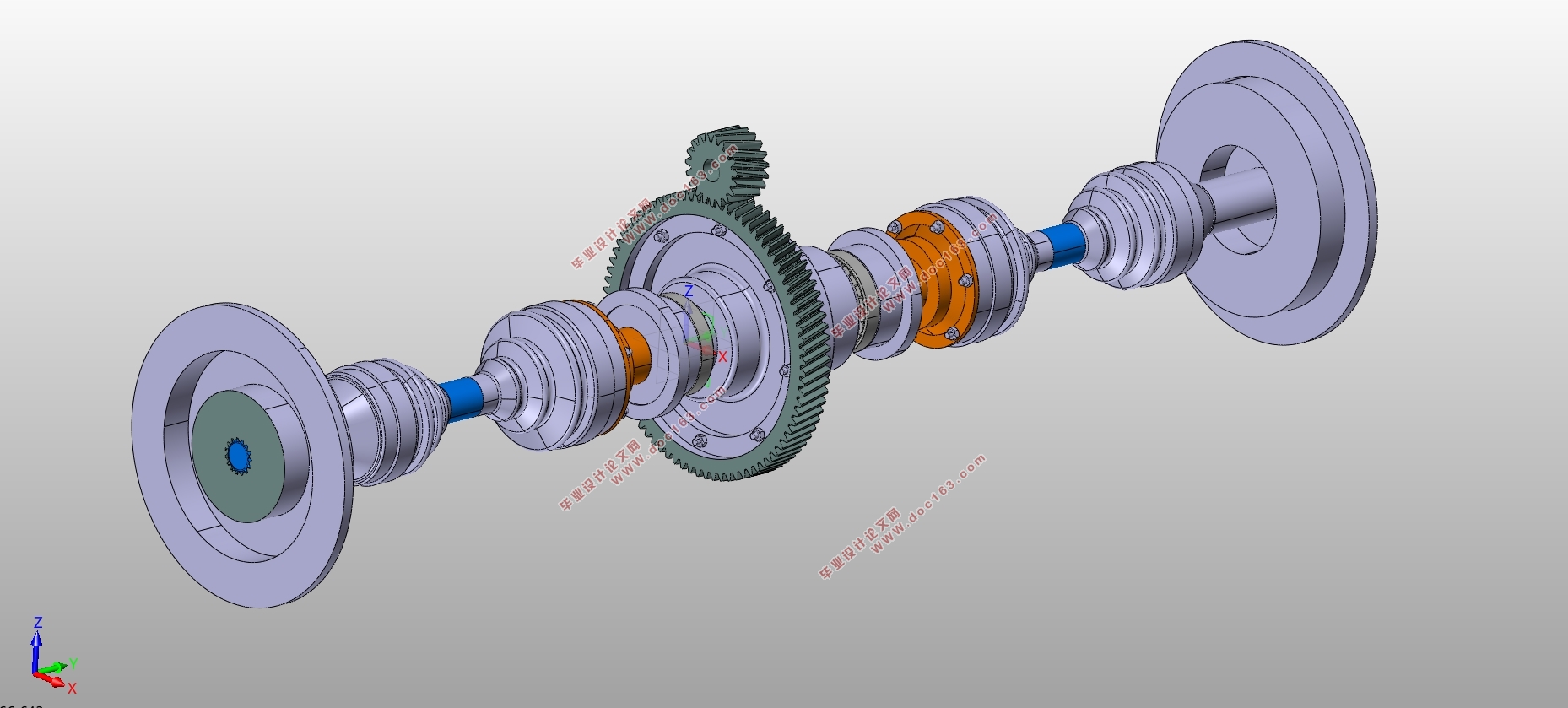
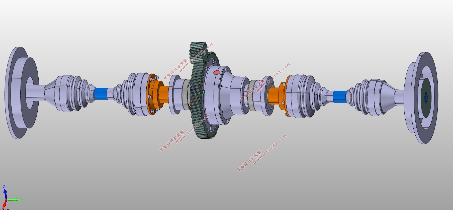
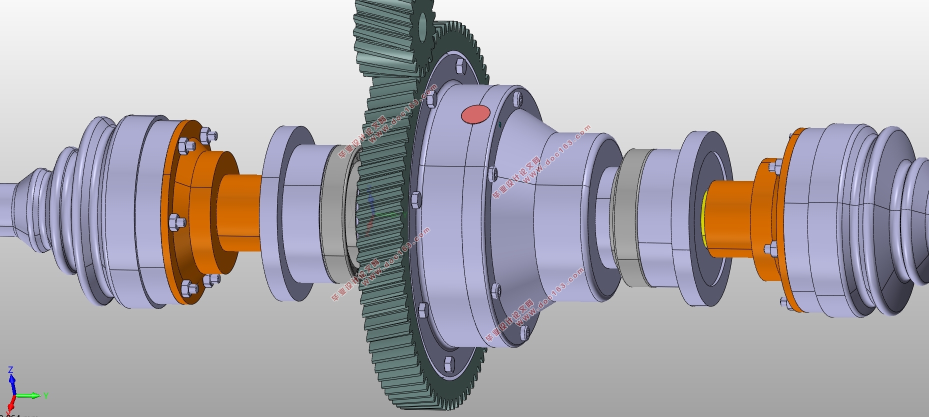
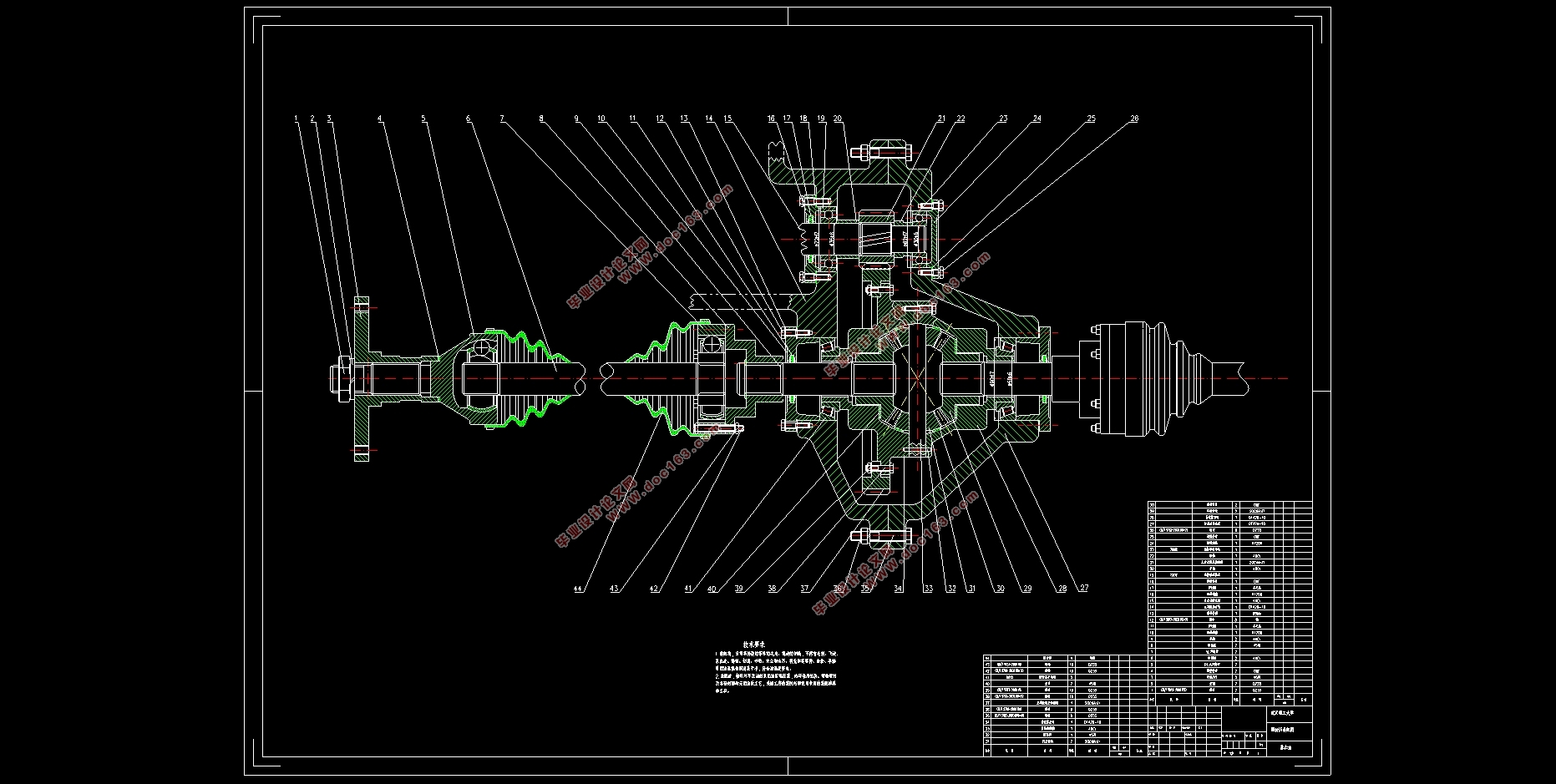
杰德轿车驱动桥设计(含CAD零件装配图,CATIA三维图)(任务书,开题报告,文献摘要,外文翻译,论文说明书11000字,CAD图10张,CATIA三维图)
摘要
驱动桥当车辆在行驶时不仅要承载它的 ,还要负担从地面传递而来的铅锤力等,这些力一般通过车轮以及悬架等结构到桥身。而且驱动桥不同于普通车桥的地方便在于它的所处位置是直接与动力输出所关联,所以它需要为其传递转矩,这是传动系中的最大转矩。
本文通过对以往的驱动桥设计资料进行观阅和反思后,结合自己的杰德轿车的相关参数进行了比较合理的参数和结构设计,我在查阅资料的过程中反复思考杰德轿车的前桥的运作机理,并且平时对街头的车样进行查看,在学习实车的驱动桥布置以及架构的同时,思考我单独进行驱动桥的设计时。是否能够遵循设计的要求流程,是否能够完成它该有的功能,并在完成功能的同时考虑到零件的三化。这其中的关键便在于主减速器以及差速器的设计与搭配之上,作为驱动桥的灵魂部件,这两个结构的参数决定了整个驱动桥的尺寸和位置。因而在这两个结构的参数计算过程中,我严格查阅相关资料和参考导师的意见,进行多次修改来完成它的结构设计,并对它进行参数化建模。并且在这两个结构的基础上对其他组合部件进行设计以及建模,最后得到一个完整的驱动桥的模型,后续的CAD图也严格依照实际的三维建模而来。
[资料来源:http://www.THINK58.com]
关键词:汽车 承载驱动桥 主减速器 差速器
Abstract
The drive axle is one of the four major assemblies of the car. It has a lot of parts and a complicated structure, and its performance will directly affect the performance of the whole vehicle.
In the car, the drive axle not only has to bear the load on the full load spring of the car, but also bears the plumb force and longitudinal force generated by the wheel through the wheel, the frame or the load-bearing body through the suspension. Moreover, the convenience of the transaxle from the conventional axle is that its location is directly related to the power output, so it needs to transmit torque for it, which is the maximum torque in the drive train.
After reviewing and reflecting on the past drive axle design data, this paper combines the parameters of the Jade sedan with reasonable parameters and structural design. At the same time, I also found the existing Jeddell's transaxle. The principle of structure, and through the street car to view and think, consider how I can complete a reasonable and dynamic, economical and other can basically meet the requirements of the transaxle design. The key to this is the design and matching of the final drive and the differential as the soul part of the drive axle. The parameters of these two structures determine the size and position of the entire drive axle. Therefore, in the parameter calculation process of these two structures, I strictly consult the relevant materials and the opinions of the reference instructors, and carry out several modifications to complete its structural design and parametric modeling. [来源:http://think58.com]
Key words:automobile driving axle main reducer differential half axle
[资料来源:http://www.THINK58.com]
目录
第1章 绪论 1
1.1 概述 1
1.2驱动桥研究现状 1
1.3驱动桥设计要求 1
1.4 驱动桥计算准备 2
第2章 主减速器的设计 4
[版权所有:http://think58.com]
2.1 驱动桥结构分析 4
2.2 主减速器的结构和功用 4
2.3 主减速器的类型 5
2.4 主减速器齿轮支承形式 5
2.5 主减速器参数设计 5
2.5.1 主减速比 计算 5
2.5.2 主减速器齿轮载荷计算 6
2.6 主减速器齿轮 8
2.6.1 主、从动齿轮简介 8
2.6.2 斜齿轮设计计算 9
2.6.3 主减速器齿轮参数表 12
2.7 主减速器设计小结 13
第3章 差速器设计 14
3.1差速器结构形式选择 14
3.2差速器齿轮设计 14
3.2.1 差速器齿轮参数 15
3.2.2 差速器齿轮校核 17
3.2.3 汽车差速器齿轮的参数表 20
3.3 轴承选择与校核 20
3.4 差速器设计小结 23
第4章 驱动车轮的传动装置设计 24
[版权所有:http://think58.com]
4.1 半轴的型式 24
4.2 半轴设计 24
4.3 半轴校核 25
4.3.1 校核工况 25
4.3.2 半浮式半轴计算载荷的确定: 25
4.4 半轴材料 29
4.5半轴设计小结 29
第5章 万向节及桥壳设计 31
5.1 万向节结构选择 31
5.2 万向节的材料及热处理 31
5.3 桥壳的简介 32
5.4 驱动桥壳的设计 32
5.5 万向节与桥壳设计小结 32
结论 34
致谢 36
参考文献 37
上一篇:自动驾驶通用执行机构控制系统设计(含CAD零件装配图,CATIA三维图)
