混合动力轻型客车转向传动装置三维设计(含CAD零件装配图,CATIA三维图)

1.无需注册登录,支付后按照提示操作即可获取该资料.
2.资料以网页介绍的为准,下载后不会有水印.资料仅供学习参考之用.
密 惠 保
混合动力轻型客车转向传动装置三维设计(含CAD零件装配图,CATIA三维图)(任务书,开题报告,外文翻译,论文说明书14000字,CAD图10张,CATIA三维图,答辩PPT)
摘 要
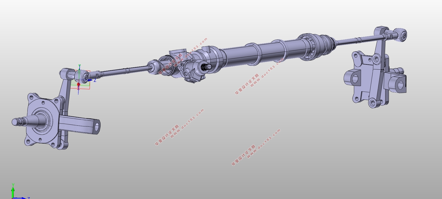
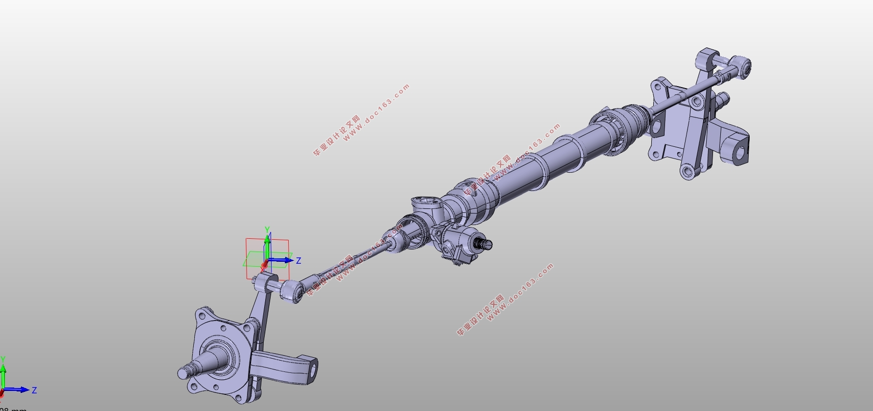
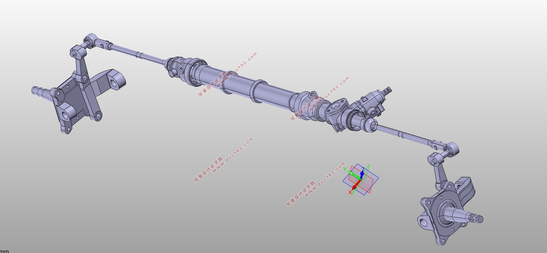
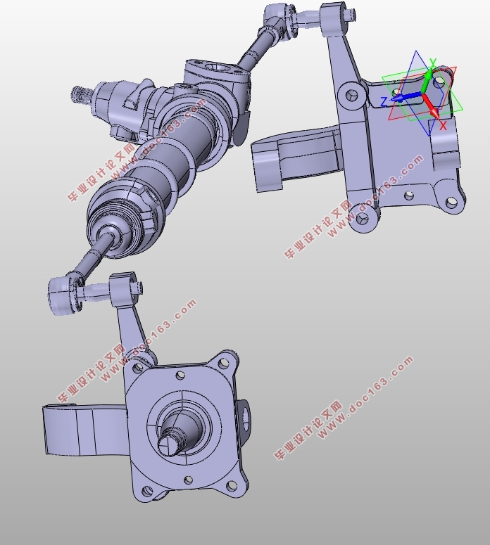
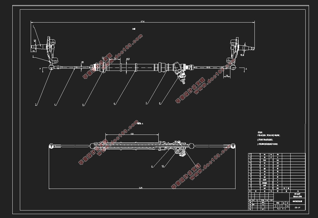
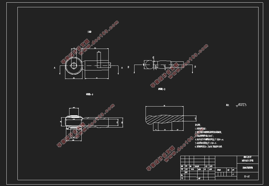
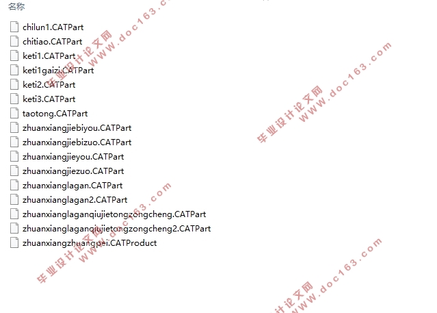
为设计转向传动装置,决定用三维扫描,逆向工程,然后用CATIA,进行三维建模及其装配,通过转化二维图,并进行标注,并用hyperworks进行校核。运用三维扫描实体得到点云,处理点云,用CATIA建立模型,在CATIA软件内进行组装,在CATIA中转化二维图后,制作剖面图,然后使用CATIA进行标注,通过设计可以得到三维模型,CAD图纸,强度校核数据及图例。通过这些方法可以任意修改产品结构,减少浪费从而提高社会生产力。
关键词:转向传动装置 三维设计 建模 CATIA 转化
Three-dimensional design of steering gear for hybrid light
passenger car
ABSTRACT
In order to design the steering gear, it was decided to use 3D scanning, reverse engineering, and then use CATIA to perform 3D modeling and assembly, transform 2D drawings, mark them, and check with hyperworks. Use 3D scanning entity to get point cloud, process point cloud, build model with CATIA, assemble in CATIA software, transform 2D drawing in CATIA, make sectional view, then use CATIA to mark, and get 3D model by design. CAD drawings, strength check data and legends. Through these methods, the product structure can be arbitrarily modified to reduce waste and improve social productivity. [资料来源:http://think58.com]
Keywords: steering gear;3D design; modeling,;CATIA; transformation
[资料来源:http://think58.com]

[资料来源:www.THINK58.com]
目 录
摘 要 I
ABSTRACT II
目 录 III
第一章 绪论 1
1.1研究意义 1
1.2国内研究 1
1.3国外研究 1
1.4转向系统 2
第二章 转向传动装置CATIA建模 3
2.1逆向工程 3
2.2 CATIA三维建模功能的分析和使用 3
2.3转向节臂的制作过程 8
2.4转向节制作过程 11
2.4齿轮制作过程 15
2.5零件 17
第三章 装配设计 18
第四章 三维图转成为工程制图 21
4.1在CATIA导出图形 21
4.2导入CAD中修改 23
4.3 CAD图纸举例 24
第五章 转向节 拉杆计算校核 27
5.1转向节 27
5.2转向拉杆 34
5.3 HYPERWORS简单过程 34
第六章 设计经济 38
第七章 总结与展望 39
参考文献 40
致谢 42
上一篇:哈弗H2前悬架系统几何重构及悬架性能分析(含CAD图,CATIA三维图)
下一篇:混合动力轻型客车驱动桥总成三维设计(含CAD零件图装配图,CATIA三维图)
