基于单片机的摄像镜头控制电路设计(含电路图)

1.无需注册登录,支付后按照提示操作即可获取该资料.
2.资料以网页介绍的为准,下载后不会有水印.资料仅供学习参考之用.
密 惠 保
基于单片机的摄像镜头控制电路设计(含电路图)(任务书,论文11500字)
摘 要
随着计算机的发展,随着图像采集处理技术的进步和社会的发展,其被广泛的运用于社会社交,远程医疗及实时监控等各个方面。图像采集是一种非接触式的检测方法,可应用于工业、民用等许多领域。摄像镜头是图像采集和图像处理的基础,关系到测量的精度与速度。基于单片机控制的摄像头可根据周围环境,实现对摄像镜头自身参数的调节,获取更去清楚和清晰的图像。因此,具有广阔的市场应用发展前景。
本文利用AT89C51单片机实现的摄像镜头控制系统,以H6Z0812M的控制为例,对光圈、变焦和聚焦的控制方法进行分析和控制电路设计。本地端采用液晶显示实时的控制信息,远端采用串口传输技术进行控制命令的下发,实现坑了摄像镜头的远程控制和本地调节功能。硬件设计完成了最小系统、串口通讯、液晶显示、控制电路等模块的硬件设计。并在硬件平台的基础上,实现各个功能模块的软件功能。
关键词:单片机;摄像镜头;串口通讯;液晶显示
Abstract
With the development of computer, with image acquisition processing technical progress and social development, which is widely used in social, telemedicine and real time monitoring and other aspects. Image acquisition is a kind of non-contact detection method can be used in industrial, civil and other many fields. Camera lens is image measurement and image processing based and related to the measurement accuracy and speed. According to the surrounding environment, the realization of the camera lens parameters adjustment, obtain more to clear and clear images. Therefore, a broad market application prospect is based on single-chip microcomputer to control the camera. [资料来源:http://www.THINK58.com]
The AT89C51 single chip microcomputer to realize camera control system. In the cases of the control H6Z0812M, of aperture, zoom and focus control method for analysis and design of the control circuit. Local side of the liquid crystal display information real-time control, distal by serial transmission technology, control command issued, realization of pits the camera remote control and local regulatory function. Hardware design is completed, the minimal system, serial communication, LCD display, the hardware design of the control circuit modules. And on the hardware platform based on, each function module of the software function.
Key words: Single chip microcomputer; camera lens; serial port communication; LCD display
2.1 设计目标
本设计需要实现对三可变摄像头的整体控制,具体需要完成的控制任务如下:
1)完成三可变(光圈、变焦和聚焦调节)镜头控制电路设计;
2)完成串行通信电路设计;
3)完成中心控制电路设计;
4)完成执行电路模块设计; [资料来源:http://think58.com]
5)实现摄像头控制电路的软件和硬件电路设计。
2.2设计思想
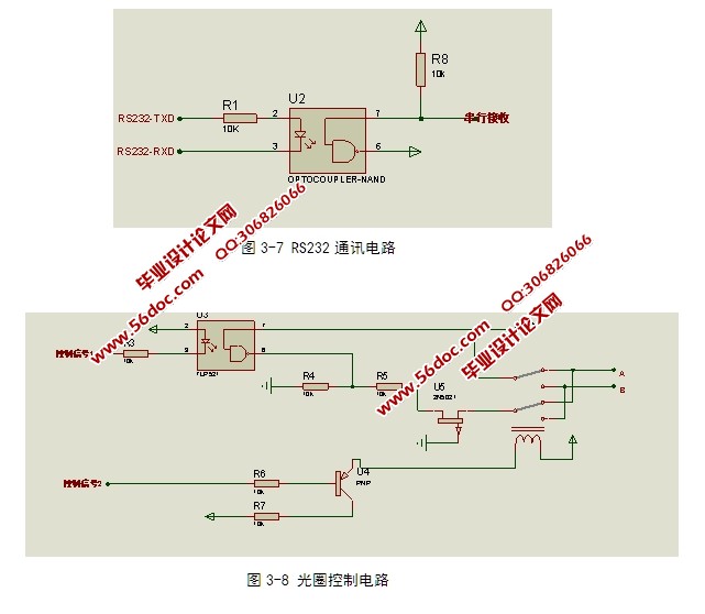
根据系统目标可知,系统需要实现硬件功能输入命令的采集和输出光圈、变焦和聚焦的控制。设计中以computer镜头 H6Z0812M为研究对象,该款摄像头具备光圈、变焦和聚焦可调的功能。它对外接线共有8根其中,两根用于外接12V电源;AB两根线用于控制光圈、CD两根线用于控制变焦、EF两个线用于控制聚焦。以光圈控制为例当A-B>12V时,光圈增大;当B-A>12V时光圈减小,通过控制AB之间的压差可以实现光圈的增大和减小控制[2-5];
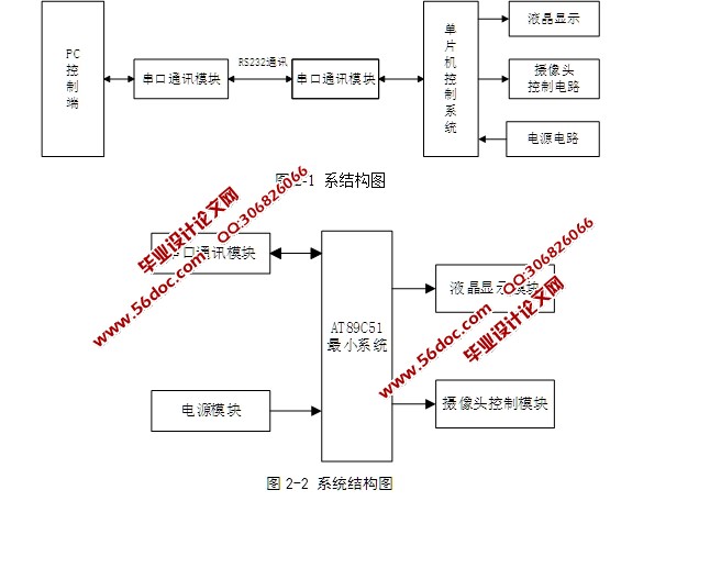
通过对整体设计目标进行评估设计中选择单片机作为核心的控制芯片,通过扩展串口通讯电路、执行电路和镜头控制电路设计。通过软件编程控制各个功能模块协调工作,完成摄像头控制电路的软件和硬件设计要求。


目 录
1 绪论 1
2系统整体设计方案 2
2.1 设计目标 2
2.2设计思想 2
2.2.1硬件实现原理 2
2.2.2软件实现原理 2
2.2.3系统框图 3 [资料来源:http://THINK58.com]
2.3 主要器件选型 3
2.4 系统框架 5
3硬件电路设计 6
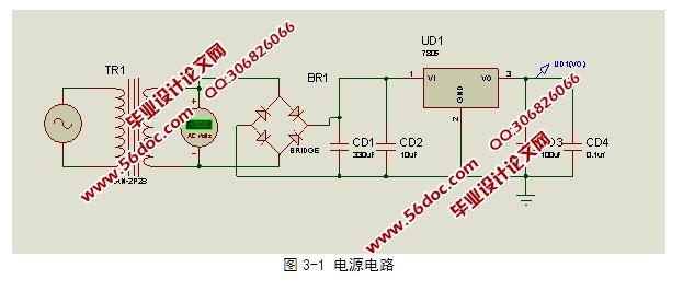
3.1 电源电路 6
3.2单片机最小系统 7
3.3 液晶显示电路设计 10
3.4串口通讯电路设计 11
3.5控制电路设计 12
4软件设计 14
4.1开发环境介绍 14
4.2主程序设计 14
5系统调试 16
5.1 调试步骤 16
5.2硬件调试 16
5.3 软件调试 17
结 论 18
参考文献 19
致谢 20
