
大型重载机械手控制系统设计与分析(含CAD图)
1.无需注册登录,支付后按照提示操作即可获取该资料.
2.资料以网页介绍的为准,下载后不会有水印.资料仅供学习参考之用.
密 惠 保
大型重载机械手控制系统设计与分析(含CAD图)(任务书,开题报告,论文说明书15000字,CAD图纸3张)
摘要
机械手是能模仿人手臂的某些动作,可以按照固定程序抓取、搬运物件或操作工具的自动操作装置,驱动方式有液压传动,气压传动,电气传动以及机械传动等。本文在通过对于给定的大型重载机械手与液压驱动方式的条件下,选定设计以PLC为运动控制器核心的控制系统。
对于给定的机械手的结构和液压系统回路,对其进行分析,设计出相应的机械手控制系统——PLC为控制器的控制系统。
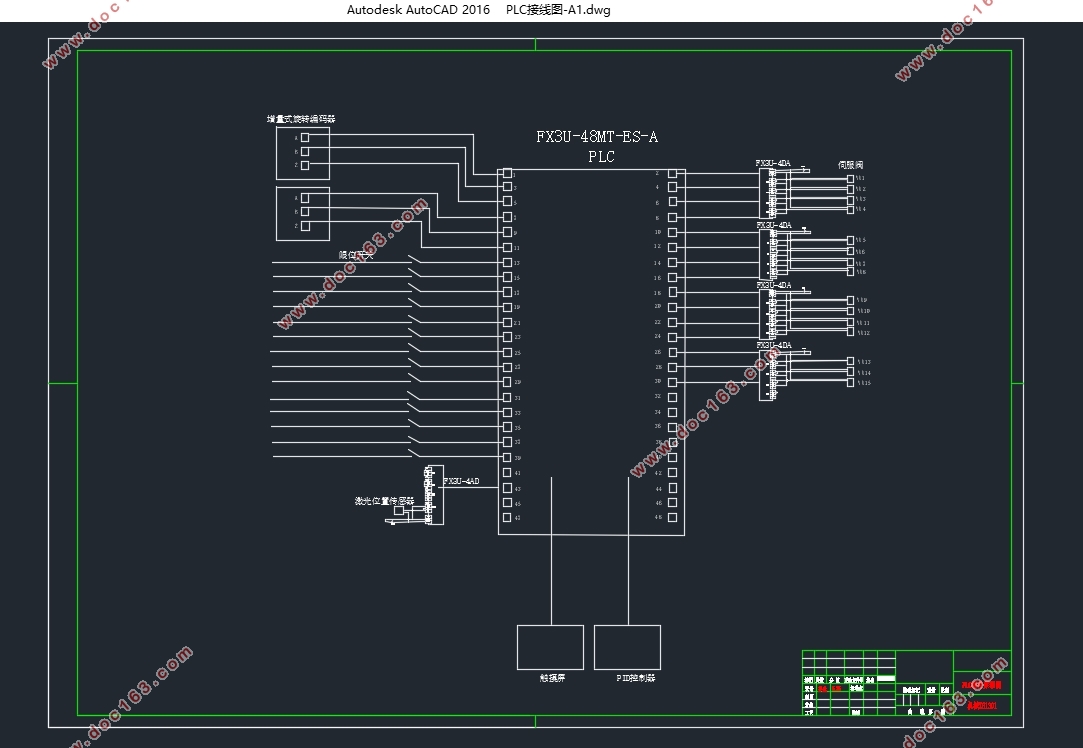
首先应对机械手的运动动作流程分析,然后针对一些要求精度高的动作,设置传感器进行反馈,因此需要进行硬件选型:选PLC型号,传感器型号,触摸屏型号,特殊模块型号等等。采用三菱的FX3U系列PLC和GT15系列触摸屏等,之后就是进行I/0点分配与触摸屏对象配置PLC对应的软元件,最后硬件接线。
软件设计则采用三菱自带的软件GX Works2编写梯形图程序,GT Designer3编写触摸屏程序,最后联合仿真,检测程序是否正确,分析机械手能否正确运动。
最后采用PID算法对阀控液压马达的速度特性进行分析,在Simulink中搭建控制系统模型然后仿真,分析得出的曲线,判断控制系统是否可以实现。 [来源:http://www.think58.com]
关键词:机械手;PLC;硬件选型;软件设计;仿真
Abstract
Robot is a kind of automatic positioning control and can be reprogrammed to change the multi-function machine, drive with hydraulic drive, pneumatic transmission, electrical control. In this paper, the control system with PLC as the core of the motion controller is selected under the conditions of a given large-scale heavy-duty manipulator and hydraulic drive mode.
For a given robot structure and hydraulic system circuit, to analyze it, design the corresponding robot control system - PLC for the controller control system.
First of all, should deal with the movement of the robot movement process analysis, and then for some of the requirements of high precision action, set the sensor feedback, so the need for hardware selection: select PLC model, sensor model, touch screen models, special module models and so on. Using Mitsubishi FX3U series PLC and GT15 series touch screen, followed by I / 0 point distribution and touch screen object configuration PLC corresponding to the device, the last hardware wiring.
And then in the Mitsubishi software GX Works2 on the preparation of ladder program, GT Designer3 write touch screen program, the final joint simulation, testing procedures are correct, analysis of the robot can move correctly.
Finally, the PID algorithm is used to analyze the velocity characteristics of the valve-controlled hydraulic motor. The control system model is set up in Simulink and then simulated and analyzed to determine whether the control system can be realized.
Key Words:Manipulator;PLC;Hardware selection;software design;Simulation
机械手结构分析
由于本论文只涉及机械手控制系统的设计,所以机械手整体结构由第三方提供,对于给定的大型重载机械手的主体结构(如图2.1所示),由一个基座水平移动导轨,4个关节,分别为腰部回转关节、肩部旋转关节、肘部旋转关节,以及腕部回转关节。末端结构为两个机械抓手,用于抓取物料和装载。
本机械手的手爪是机械手结构的关键设计,如图2.2所示。它采用内外上下四个小圆柱组成,外侧圆柱大于里侧圆柱,抓紧时,外侧圆柱向内移动,与里侧小圆柱达到夹紧长杆的目的,然后在拧紧装配时,通过四个圆柱同时旋转,带动长杆拧紧,可以减少相对摩擦,提高机械手的使用寿命和精度。
[来源:http://think58.com]
这种机械手不仅结构简单、紧凑,负载能力强,稳定性强,而且有较大的工作范围,具有较高的重复精度。
机械手的实际搬运动作就是由沿底部基座水平移动、绕基座的腰部回转、肩关节的旋转、肘关节的旋转、腕关节的回转等四个简单运动复合而成,在加上机械抓手的抓紧、松开以及拧紧构成一个具体的搬运过程。
机械本体的设计规格如表2 1所示。
表2 1机械本体设计规格
名称 内容
构造 5自由度垂直多关节型
负载 330KG
重复定位精度 -0.5~0.5mm
容许惯性矩(〖GD〗^2⁄4) 腕部回转轴 200kg⁄m^2
动作范围 水平导轨 0~3M
腰部 -180~180°
肩部 0~70°
肘部 0~90°
腕部 0~90°
最大速度 基座水平导轨 0.3m/s [资料来源:http://think58.com]
腰部 0.654rad/s,37.5°⁄s
肩部 1.256rad/s,72°⁄s
肘部 2.617rad/s,150°⁄s
腕部 3.488rad/s,199.95°⁄s
[资料来源:http://think58.com]

[版权所有:http://think58.com]
目录
摘要 I
Abstract II
目录 III
第 1 章 绪论 1
1.1研究的目的与意义 1
1.2国内外研究现状 1
1.2.1机械手的研究现状 1
1.2.2 PLC控制系统的研究现状 2
1.3论文主要研究的内容 3
第 2 章 机械手控制系统方案设计 4
2.1机械手结构分析 4
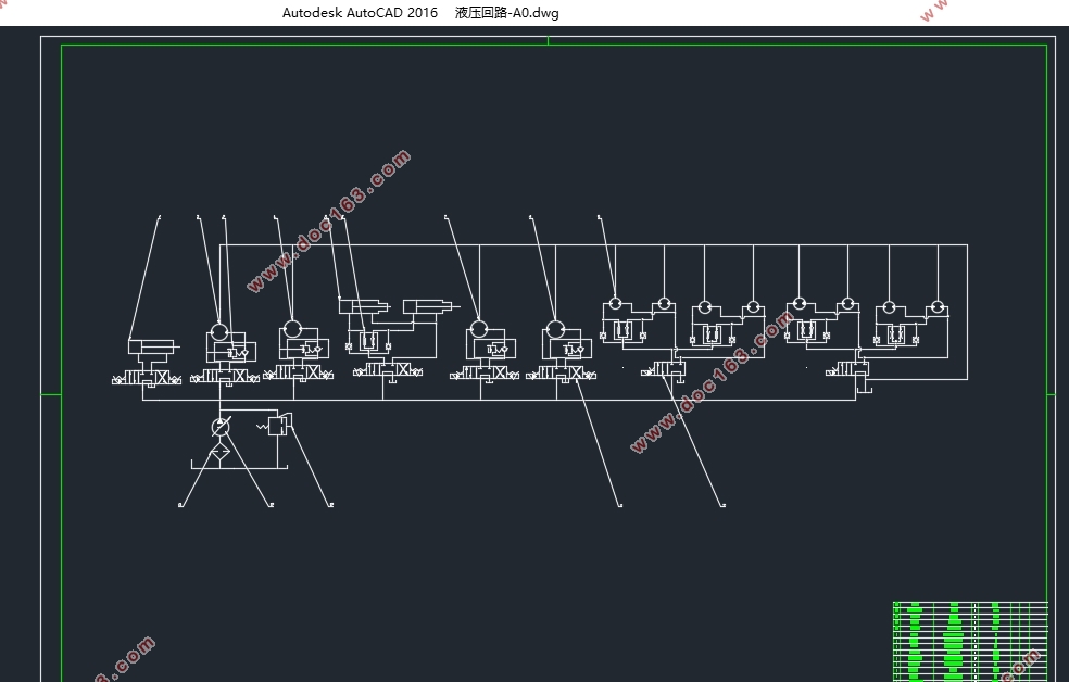
2.2机械手液压系统分析 5
2.3机械手控制系统方案 7
2.3.1机械手控制方案 7
2.3.2机械手运动方案 7
第 3 章 机械手控制系统硬件设计 9
3.1系统PLC的选型 9
3.1.1可编程逻辑控制器介绍 9
3.1.1.1可编程逻辑控制器的结构 9
3.1.1.2可编程逻辑控制器工作原理 10
3.1.2 PLC的选型 11
3.2传感器的选型 13
3.2.1位移传感器的选型 13
3.2.2位置传感器选型 14
3.3触摸屏的选型 14
3.4特殊模块的选型 15
3.5 I/0点分配与外部硬件接线图 16
第 4 章 机械手控制系统软件设计 20
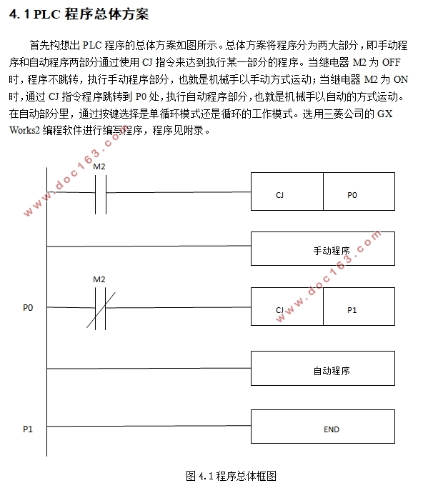
4.1 PLC程序总体方案 20
4.2手动操作程序 21
4.3自动操作程序 24
4.4触摸屏程序 26
4.5 PLC控制系统软件仿真 27
第 5 章 控制系统的算法与仿真 28
5.1系统的组建和建模 28
5.1.1阀控液压马达系统建模 28
5.1.2阀控液压马达系统的传递函数 29
5.2控制系统的PID算法 30
5.3控制系统的SIMULINK模型与仿真 31
第 6 章 总结与展望 34
[资料来源:http://www.THINK58.com]
6.1总结 34
6.2展望 34
参考文献 35
附录 37
致谢 41