
无人驾驶智能车转向系统设计(含CAD零件图装配图)
1.无需注册登录,支付后按照提示操作即可获取该资料.
2.资料以网页介绍的为准,下载后不会有水印.资料仅供学习参考之用.
密 惠 保
无人驾驶智能车转向系统设计(含CAD零件图装配图)(论文说明书12000字,CAD图5张)
摘要
随着互联网技术在各行各业蓬勃发展,无人驾驶技术正成为全球顶尖设计师想要拿下的桂冠。然而,目前无人驾驶技术的研究遇到许多瓶颈,无人驾驶转向系统的设计是其中最关键的部分之一。
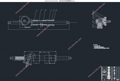
本文介绍了一个无人驾驶智能车的转向系统设计过程,这种转向系统分为两大块。其中,控制部分是利用传感器、数据采集系统和车载电脑完成道路信息采集和决策,并将指令输送给机械操纵机构实现自主转向。机械部分是以电机为动力源,通过齿轮传动,带动齿轮齿条式转向器运作,随之带动转向轴等操纵机构转动。本文首先分析了国内外无人驾驶转向系统的研究现状,根据相关资料明确了设计技术路线,然后据此确定了控制部分的大体方案,具体设计了转向器类型和计算了齿轮齿条的具体参数、进行了转向梯形的基本优化、完成了操纵机构防伤和电机设计等工作,最后在一些必要的部分完成了相关零件的应力校核等工作。
关键词:无人驾驶;转向系统;齿轮齿条式转向器;转向梯形优化
Abstract
With the rapid development of Internet technology in all walks of life, driverless technology is becoming the crown of the world's top designers. However, the current research on driverless technology has encountered many bottlenecks, and the design of the driverless steering system is one of the most critical parts. [资料来源:www.THINK58.com]
This paper introduces the steering system design process of an unmanned smart car, which is divided into two large blocks. Among them, the control part uses the sensor, the data acquisition system and the on-board computer to complete the road information collection and decision-making, and delivers the command to the mechanical control mechanism to realize the autonomous steering. The mechanical part is based on the motor as the power source. Through the gear transmission, the rack and pinion steering gear is driven to operate, and then the steering mechanism such as the steering shaft is driven to rotate. This paper first analyzes the research status of the unmanned steering system at home and abroad, and clarifies the design technical route based on the relevant data. Then, based on this, the general scheme of the control part is determined, and the steering gear type and the specific parameters of the rack and pinion are calculated. The basic optimization of the steering trapezoid was carried out, the anti-injury of the operating mechanism and the motor design were completed, and finally the stress check of the relevant parts was completed in some necessary parts.
Keywords: driverless; steering system; rack and pinion steering; steering trapezoidal optimization
转向系统相关参数确定
经过前期调研,本设计整车参数的的目标车型即为宝骏E200,相关参数如表2.1所示:
表2.1宝骏E200整车相关参数
尺寸参数 长/宽/高 2479mm/1526mm/1616mm
轴距 1600mm
前轮轮距 1310mm
质量参数 整备质量 842kg
满载质量 1022kg
其他可能影响转向设计参数 驱动方式 前置前驱
助力类型 电动助力
前悬架类型 麦弗逊式独立悬架
为了保证校核具有良好的通过性,在最大转角时的最小转弯半径为轴距的2-2.5倍。根据整车数据,设计转向半径为R_min=3600m,主销间距定位K=825mm,前轮轮距B_1=1310mm。
由此,可依据阿克曼转角关系得转向轮外轮最大转角为
θ_0max=arctan L/(R_min-(B_1-K)/2)=25.48˚ [版权所有:http://think58.com]
转向轮内轮最大转角为
θ_1max=arccot(cotθ_0max-K/L)=32.28˚
即转向轮外轮最大转角为25.48˚,内轮最大转角为32.28 ˚。


目录
第一章绪论 1
1.1国外研究现状分析 1
1.2国内研究现状分析 2
1.3研究目的及意义 2
第二章转向系统技术方案 4
2.1转向系统简述 4
2.2无人驾驶转向系统设计方法 4
[资料来源:www.THINK58.com]
2.3转向系统相关参数确定 4
2.4转向系统技术方案选定 5
第三章转向器的设计 7
3.1确定转向器类型 7
3.2齿轮齿条转向器基本设计 8
3.2.1输入输出形式 8
3.2.2齿轮齿条形式选择 8
3.2.3布置形式 9
3.3转向器具体参数设计 9
3.3.1转向系统载荷和传动比计算 9
3.3.2齿轮齿条机构设计要求 10
3.3.3齿轮齿条具体参数设计 11
3.3.4 转向器校核 13
第四章转向传动机构 15
4.1概述 15
4.2阿克曼条件 15
4.3确定优化的目标函数 16
4.3.1约束条件 17
4.3.2函数优化结果 17
4.4转向传动机构部件的设计 17
4.4.1球头销 17
4.4.2转向横拉杆 18
第五章操纵机构 19
第六章电机及相关件设计 20
6.1电机布置位置 20
6.2电机选型 20
6.3电机齿轮参数 21
6.4分离器设计 21
结论 23
参考文献 24
致谢 25
[资料来源:http://THINK58.com]
下一篇:某轻型货车转向系统设计(含CAD零件装配图,CATIA三维图)