
2100T柴油配气机构设计与仿真(含CAD零件图装配图,CATIA三维图)

1.无需注册登录,支付后按照提示操作即可获取该资料.
2.资料以网页介绍的为准,下载后不会有水印.资料仅供学习参考之用.
密 惠 保
2100T柴油配气机构设计与仿真(含CAD零件图装配图,CATIA三维图)(任务书,开题报告,文献摘要,外文翻译,论文说明书13000字,CAD图5张,CATIA三维图,答辩PPT)
摘要
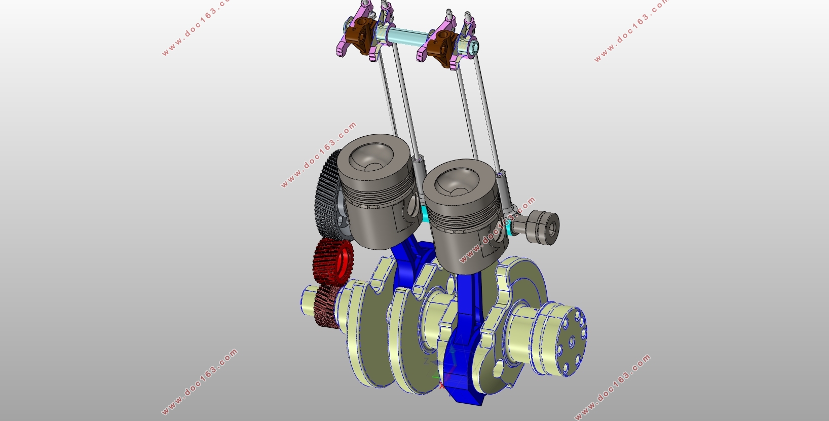
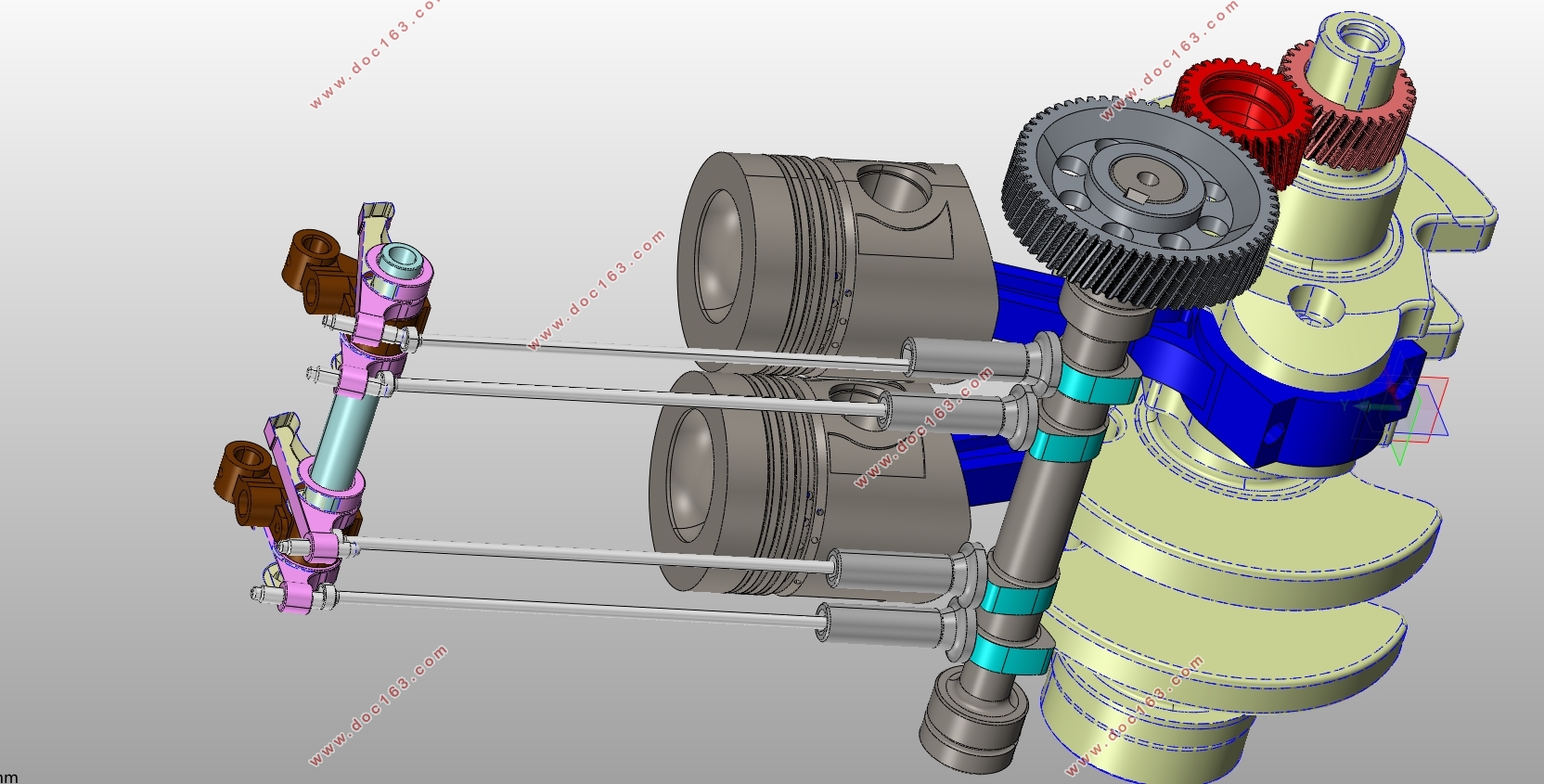
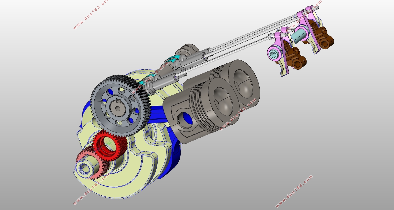
配气机构是柴油机的重要组成部分之一。它的作用是按照内燃机每个气缸的工作次序和配气相位完成进气和排气过程,并在压缩行程和做功行程时保证气缸的密闭性。我们对配气机构有以下要求:内燃机应具有良好的换气性能,有较高的冲量系数,并且可靠性好、动力性好、经济耐用。近二十年来,市场要求发动机变得更加高效,且转速更快,人们对配气机构性能指标的要求也越来越高,在更高效和高速的条件下,配气机构可以更加可靠地运行。
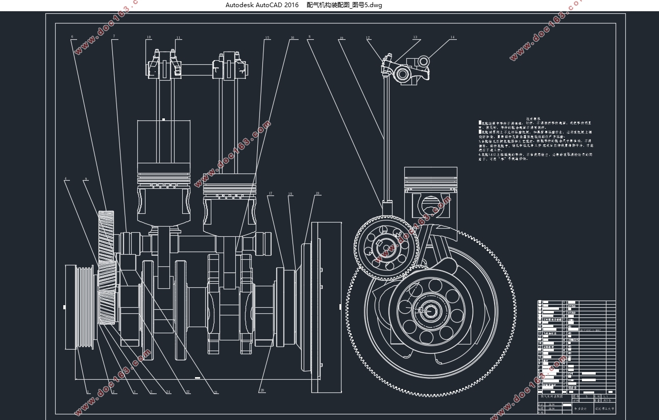
本文主要是先设计三种常见的配气凸轮的轮廓曲线,再代入原有的2100T柴油机配气机构并进行动力学分析,比较每个凸轮型线的模拟结果以获得最佳解决方案。首先,利用CATIA将2100T的原始配气机构的3D模型建立出来,再利用CAD将2100T柴油机的原始凸轮曲线进行数据导出,经过计算得到它的转角升程表,利用CATIA在添加零件材料后的到零件的质量、惯性矩、弹性模量、泊松比等参数,最后将这些参数导入AVL EXCITE Timing Drive软件中,以创建配气机构多质量模型。
改变凸轮型线为原始四圆弧凸轮曲线,多项式高次方方程曲线,等加速度方程曲线进行动力学特性对比,并分析不同凸轮型线对气门运动规律、气门落座力,凸轮与挺柱接触应力等参数的影响。确定最佳的一组轮廓为多项式高次方曲线,与原来的凸轮配置相比,有了很大的改进。
[资料来源:THINK58.com]
关键词:2100T柴油机;配气机构;动力学分析;凸轮型线优化设计
Abstact
The valve train is one of the important parts of the engine. Its role is to complete the intake and exhaust processes according to the working sequence and the valve phase of each cylinder of the internal combustion engine, and to ensure the tightness of the cylinder during the compression stroke and power stroke. The performance of the gas distribution mechanism mainly has the following requirements: the internal combustion engine should have good gas exchange performance, a high impulse coefficient, and good reliability, dynamic performance, economy, and durability. In the past two decades, the market has demanded that the engines become more efficient, and the speed is faster, and people's requirements for performance indicators of the counterfeit mechanisms are also getting higher and higher. Under more efficient and high-speed conditions, the valve trains can operate more reliably.
This paper mainly designs the three common profiles of the gas distribution cams, and substitutes them into the existing 2100T diesel engine gas distribution mechanism and performs dynamic analysis. The simulation results of each cam profile are compared to obtain the optimal solution. First, the 3D model of the 2100T original valve train was established using CATIA, and then the original cam curve of the 2100T diesel engine was exported using CAD data, and its corner lift table was calculated to use CATIA to add the part material. Parts such as mass, moment of inertia, elastic modulus, Poisson's ratio, etc., are imported into the AVL EXCITE Timing Drive software to create a multi-mass model of the valve train.
[资料来源:THINK58.com]
Change the cam profile to the original four-arc cam curve, polynomial higher-order square equation curve, isokinetic equation curve to compare the dynamic characteristics, and analyze the different cam profiles on the valve movement law, valve seating force, cam and tappet contact stress The influence of other parameters. Determining the best set of contours for the polynomial higher-order square curve has been greatly improved compared to the original cam configuration.
Key words:2100T diesel engine;valve train;dynamic analysis;cam profile design
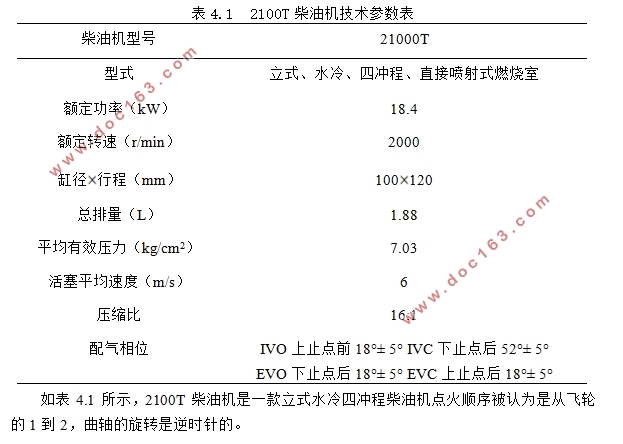
表4.1 2100T柴油机技术参数表
柴油机型号 21000T
型式 立式、水冷、四冲程、直接喷射式燃烧室
额定功率(kW) 18.4
额定转速(r/min) 2000
缸径 行程(mm)
100 120
总排量(L) 1.88
平均有效压力(kg/cm2) 7.03
活塞平均速度(m/s) 6
压缩比 16:1 [版权所有:http://think58.com]
配气相位 IVO上止点前18°± 5° IVC下止点后52°± 5°
EVO下止点后18°± 5° EVC上止点后18°± 5°
如表4.1所示,2100T柴油机是一款立式水冷四冲程柴油机点火顺序被认为是从飞轮的1到2,曲轴的旋转是逆时针的。
[资料来源:www.THINK58.com]

 [资料来源:THINK58.com]
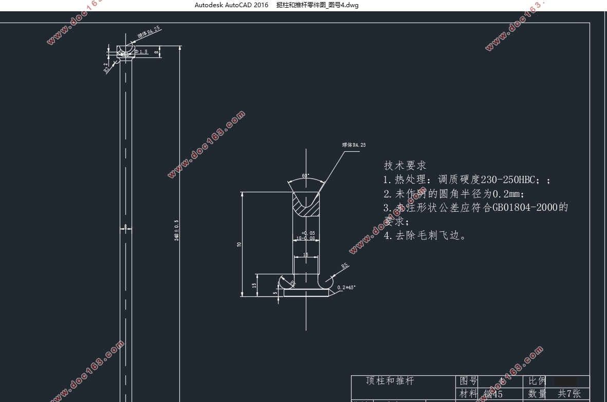
目录
摘要 i
Abstact ii
第 1 章 绪论 1
1.1研究背景及意义 1
1.2配气机构动力学分析国内外研究现状 1
1.3配气机构新技术 2 [资料来源:http://THINK58.com]
1.4主要研究内容 2
第 2 章 配气机构分析的理论基础 4
2.1配气机构动力学模型 4
2.2配气凸轮优化设计方法和评价指标 5
2.3本章小结 6
第 3 章 配气机构凸轮型线的设计 7
3.1凸轮型线缓冲段的设计 7
3.2凸轮型线工作段设计 7
3.3本章小结 11
第 4 章 配气机构动力学分析 13
4.1 AVL EXCITE Timing Drive软件介绍 13
4.2单阀系配气机构分析 13
4.3整体配气机构分析 17
4.4本章小结 26
第 5 章 总结与展望 27
5.1总结 27
5.2展望 27
参考文献 28
附录 30
致谢 35
[资料来源:www.THINK58.com]
上一篇:汽车电动尾门举升和锁扣机构设计(含CAD零件图装配图,CATIA三维图)
下一篇:智能车自主转向系统设计(含CAD图,SolidWorks三维图)