混合动力轻型客车转向传动装置三维设计(含CAD图,CATIA三维图)
1.无需注册登录,支付后按照提示操作即可获取该资料.
2.资料以网页介绍的为准,下载后不会有水印.资料仅供学习参考之用.
密 惠 保
混合动力轻型客车转向传动装置三维设计(含CAD图,CATIA三维图)(开题报告,论文说明书12000字,CAD图6张,CATIA三维图)
摘要
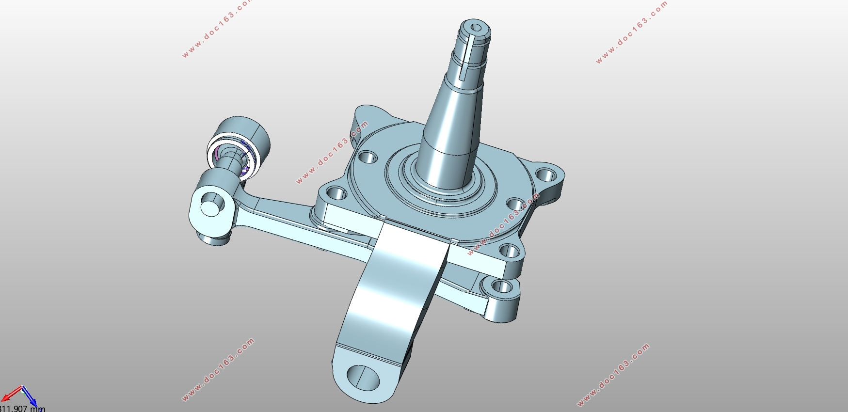
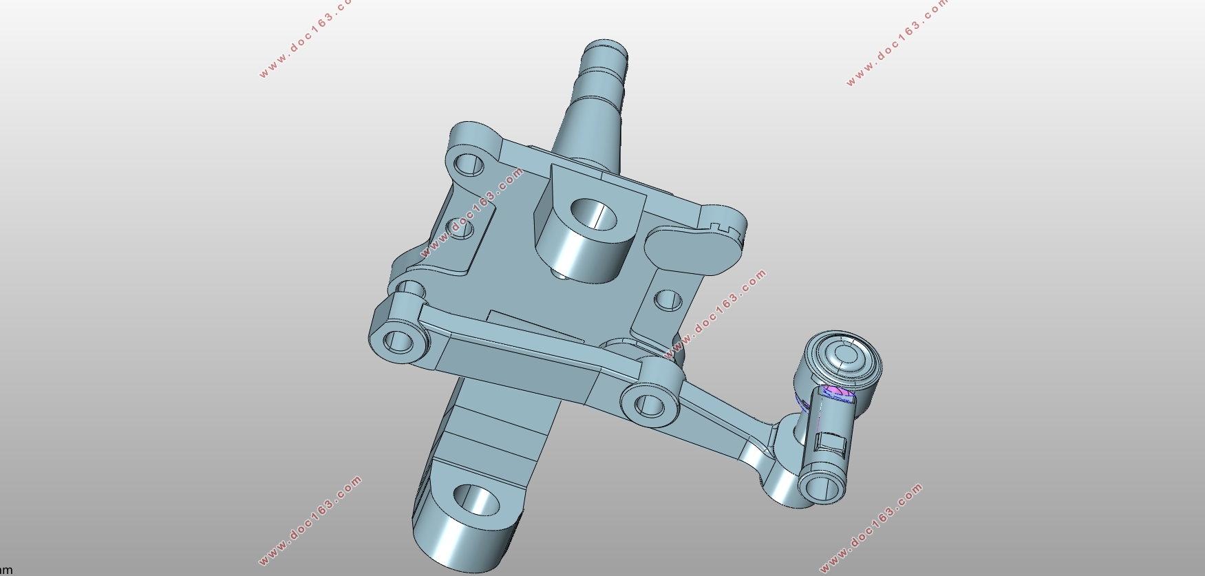
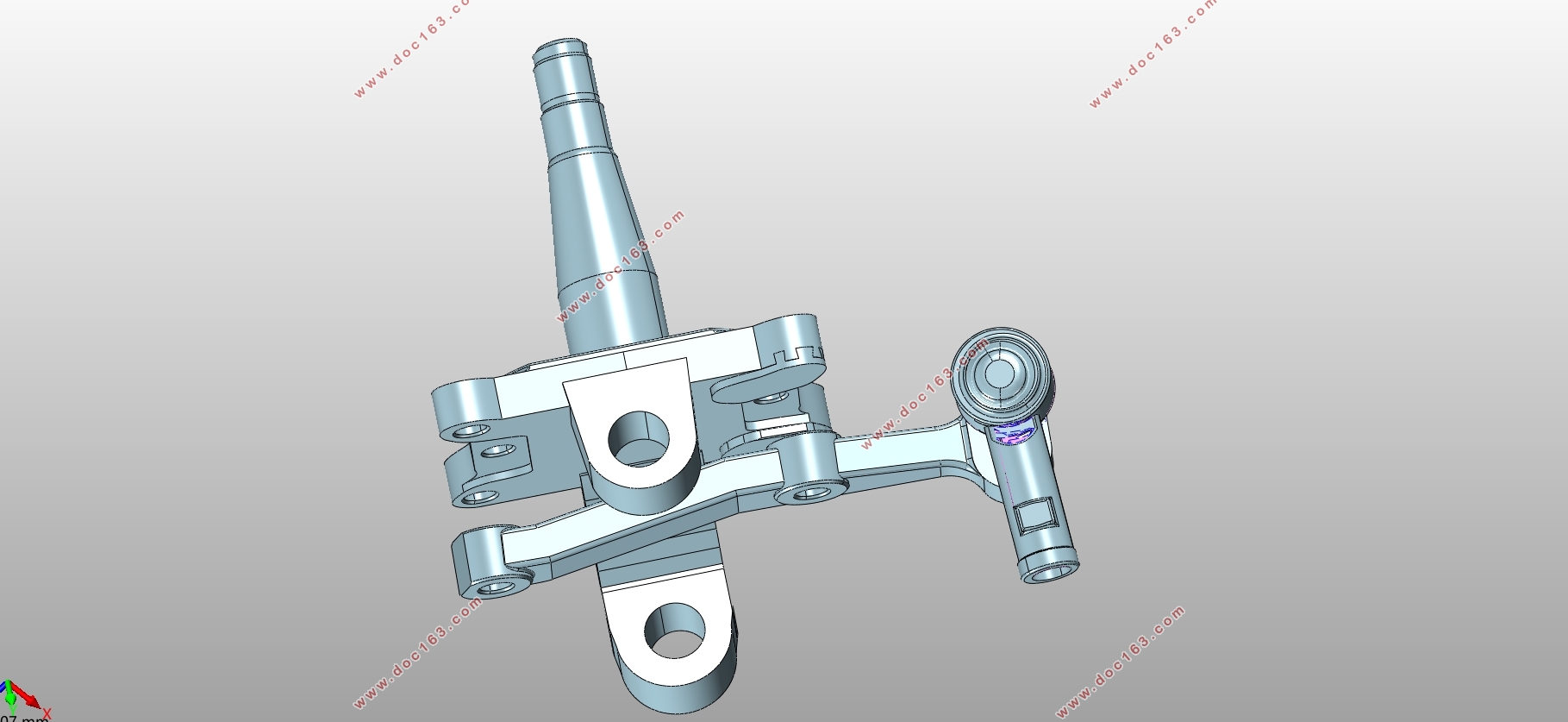
本文的课题主要方向以依维柯混合动力轻型客车为研究对象,设计混合动力轻型客车的转向传动装置,拟主要采用三维逆向建模的方法对其进行设计,即逆向工程。
本文将讲述基于CATIA设计环境下的转向传动装置的三维建模逆向重构及二维工作图设计的研究内容。设计的首要步骤是,首先需要的是用三维激光扫描设备对需要研究的模型用扫描的方式进行扫描,然后利用有截模功能的软件把获得的相关需求参数进行收集处理运算。进而对扫描数据模型使用封闭组合面进行拟合,得出处理后的三维数字模型。接着则是在CATIA环境下对已经生成模型的各零件进行装配,并修整零件错误。最后,利用输出数据,在ANSYA检查各重要零件的强度,同时在CAD中对零件的二维图进行尺寸优化。
二维工作图的设计,是继三维建模后又一道重要的工作。三维图虽然直观明了,但却不能靠它来进行机械加工。因此二维工作图的重要性得以显现。本次工作的最终目的是为了机械加工,因此前面的扫描和建模都是为后面的工程图而层层铺垫的。所以最终的工作将是在CAD中完成零件的二维图的尺寸优化,并标注必要的公差和粗糙度。 [资料来源:http://THINK58.com]
本文通过对转向传动装置的设计计算、基于CATIA环境下的三维建模逆向重构及二维工作图设计,了解了转向传动装置的整个设计过程,这为进一步改进转向传动装置提供了一定的参考依据。
关键词:逆向工程 转向传动装置 CATIA 三维扫描 三维建模
Three dimensional design of steering and driving device of hybrid light bus
Abstract
The main direction of this paper is IVECO hybrid light bus as the research object, design the steering gear of hybrid light bus, it is mainly to use 3d reverse modeling method to design it, namely reverse engineering.
This paper will describe the research content of 3d modeling reverse reconstruction and 2d work drawing design of steering gear based on CATIA design environment. The first step of design is to scan the model that needs to be studied using 3d laser scanning equipment, and then use the software with truncation function to collect the relevant requirements parameters. Then the scanning data model is used to fit the closed combination surface, and the 3d digital model is obtained. Next, in the CATIA environment, the parts that have generated the model are assembled and the parts error is trimmed. Finally, using the output data, the strength of each important part is checked in ans, and the 2d drawing of the part is optimized in CAD.
[资料来源:http://THINK58.com]
The design of two-dimensional work chart is another important work after 3d modeling. Although the three-dimensional diagram is intuitive, but it can not rely on it for mechanical processing. Therefore, the importance of the two-dimensional work chart can be revealed. The ultimate goal of this work is for mechanical processing, so the front scan and modeling are paved for behind the engineering drawings. Therefore, the final work will be to complete the dimension optimization of the 2d drawing of the part in CAD, and to mark the necessary tolerance and roughness.
Through the design calculation of the steering gear, the reverse reconstruction of 3d modeling based on CATIA and the design of two-dimensional work chart, the whole design process of the steering gear is understood, which provides a certain reference basis for further improving the steering gear.
Key words: reverse engineering; steering gear; CATIA; 3D scanning; 3D modeling
[资料来源:http://think58.com]
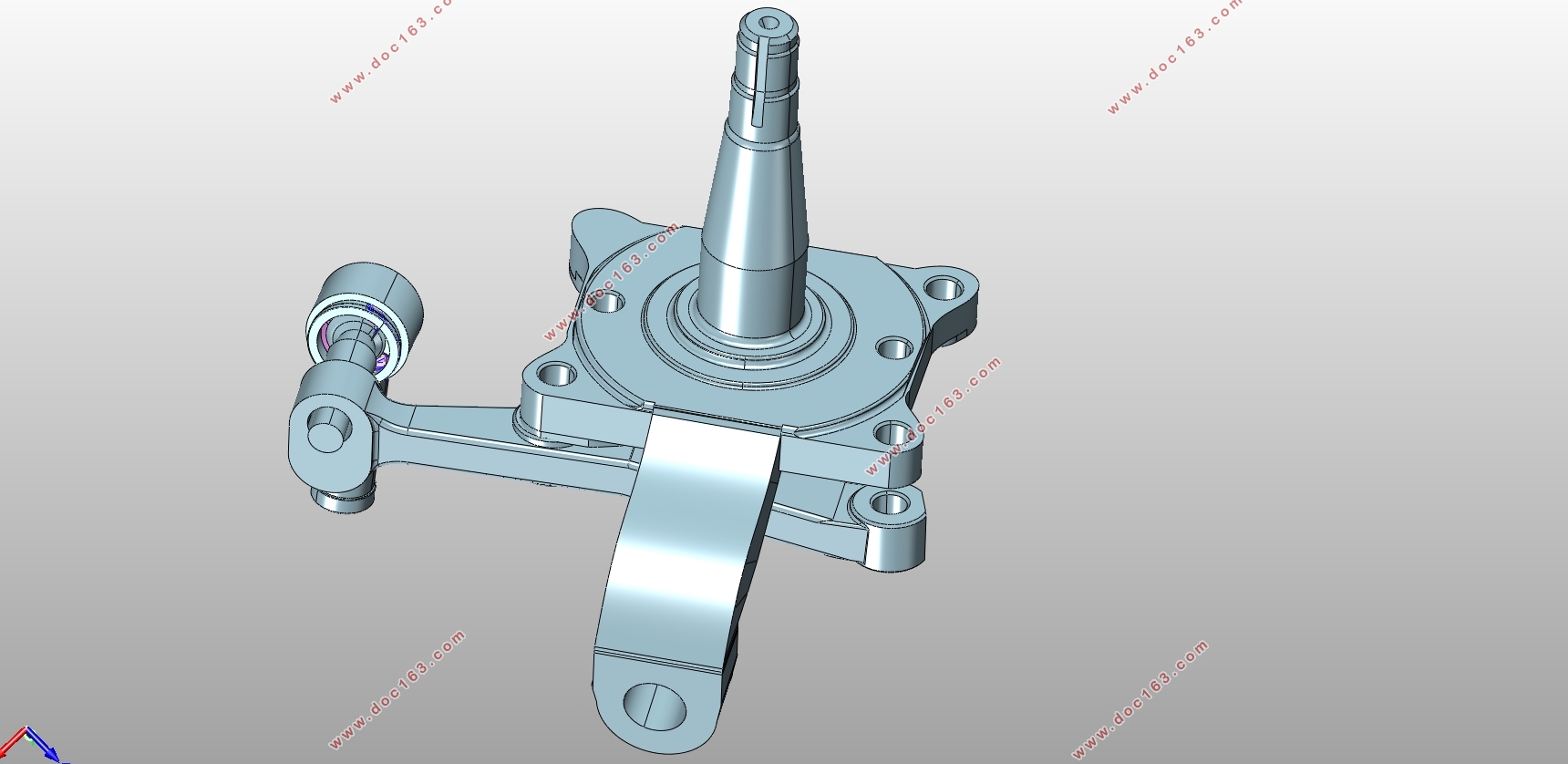
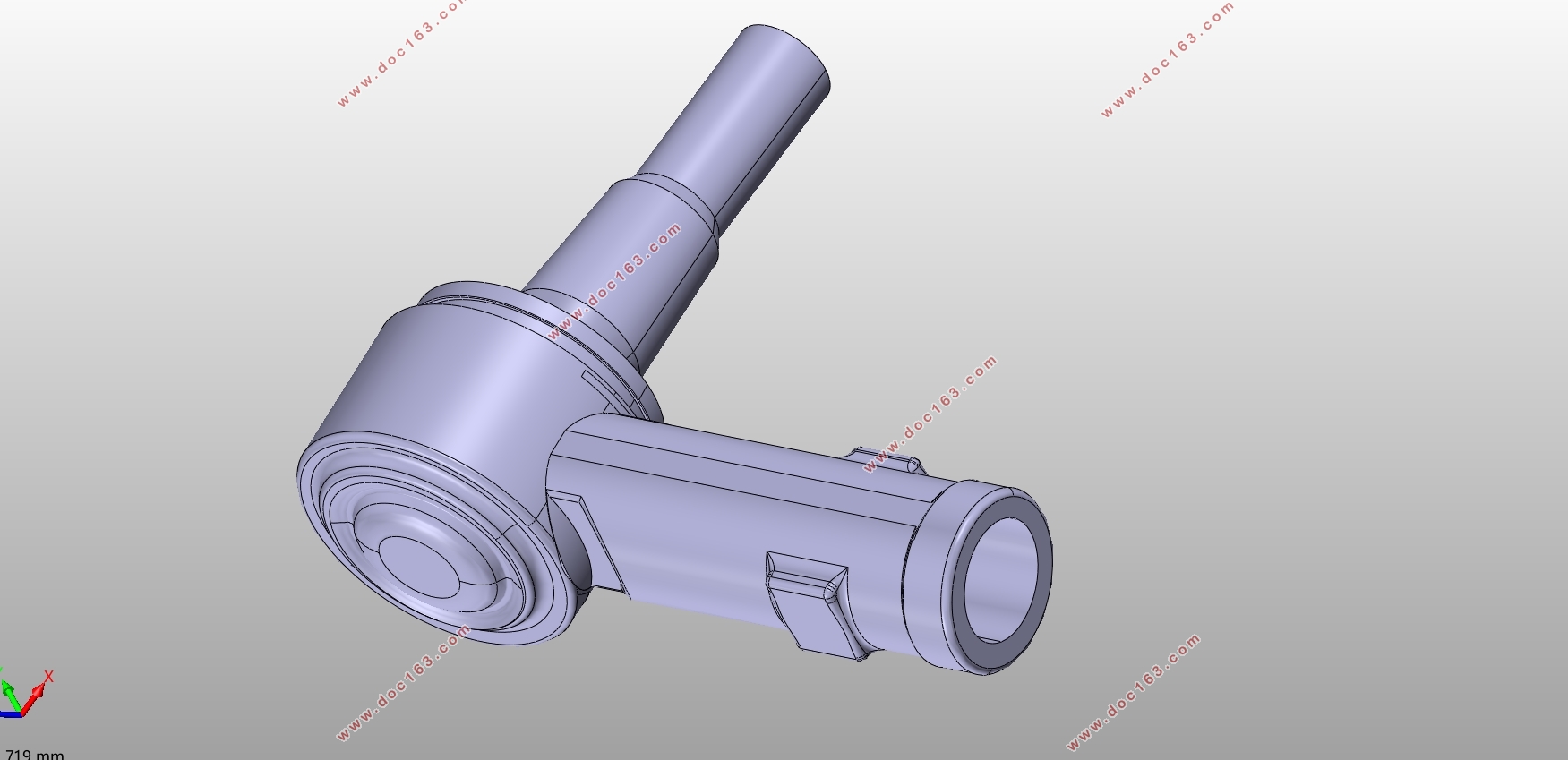 [资料来源:http://think58.com]
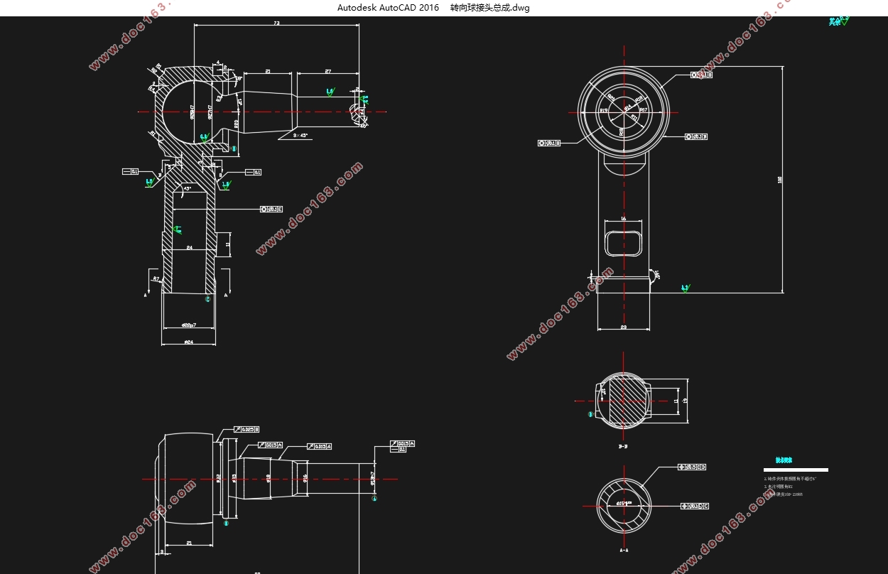
目录
摘要................................................................................................................................I
Abstract...........................................................................................................................II
[来源:http://think58.com]
第一章绪论.......................................................................................................................4
1.1研究意义...............................................................................................................1
1.2转向传动装置的分类、结构及原理...................................................................2
1.2.1 与非独立悬架相配的转向传动机构......................................................2
1.2.2 与独立悬架配用的转向传动机构..........................................................3
1.3 国内外研究现状..................................................................................................4
1.3.1 转向传动装置的国外研究现状..............................................................4
1.3.2转向传动装置的国内研究现状...............................................................5
1.3.3转向传动装置研究成果...........................................................................5
第二章基于CATIA 的转向传动装置三维建模..................................................6
[资料来源:www.THINK58.com]
2.1 CATIA 逆向工程..................................................................................................6
2.2 三维建模原理......................................................................................................6
2.2.1 三维扫描原理..........................................................................................6
2.2.2 扫描对象形态数据的获取与处理..........................................................7
2.2.3 点云数据的采集......................................................................................9
2.3点云处理.............................................................................................................10
2.3.1 数据降噪................................................................................................10
2.3.2 数据修补............................................................................................... 11
2.4 零件的曲面重构及实体化................................................................................12 [版权所有:http://think58.com]
2.4.1 基于特征创建曲面..............................................................................14
2.4.2 基于曲面的实体特征生成..................................................................16
2.5 其他零件实体化................................................................................................19
2.5.1转向节臂................................................................................................ 19
2.5.2转向拉杆球接头总成............................................................................20
2.6本章小结.............................................................................................................21
第三章 零件装配........................................................................................................22
3.1 装配文件的建立和零件的导入........................................................................22
3.2 装配约束的建立................................................................................................23
[版权所有:http://think58.com]
3.3 本章小结............................................................................................................25
第四章 三维模型转化二维视图............................................................................26
4.1 基于CATIA 的三维模型转化二维视图...........................................................26
4.2 基于CAD的二维视图修整................................................................................30
第五章 总结与展望....................................................................................................35
5.1总结.....................................................................................................................35
5.2展望.....................................................................................................................36
致谢.............................................................................................................................37
参考文献.........................................................................................................................38 [资料来源:THINK58.com]
上一篇:东风AX7手动变速器设计与计算(含CAD零件图装配图,CATIA三维图)
