某A0级轿车前悬架系统(麦弗逊式独立悬架)设计(含CAD图,CATIA三维图)
1.无需注册登录,支付后按照提示操作即可获取该资料.
2.资料以网页介绍的为准,下载后不会有水印.资料仅供学习参考之用.
密 惠 保
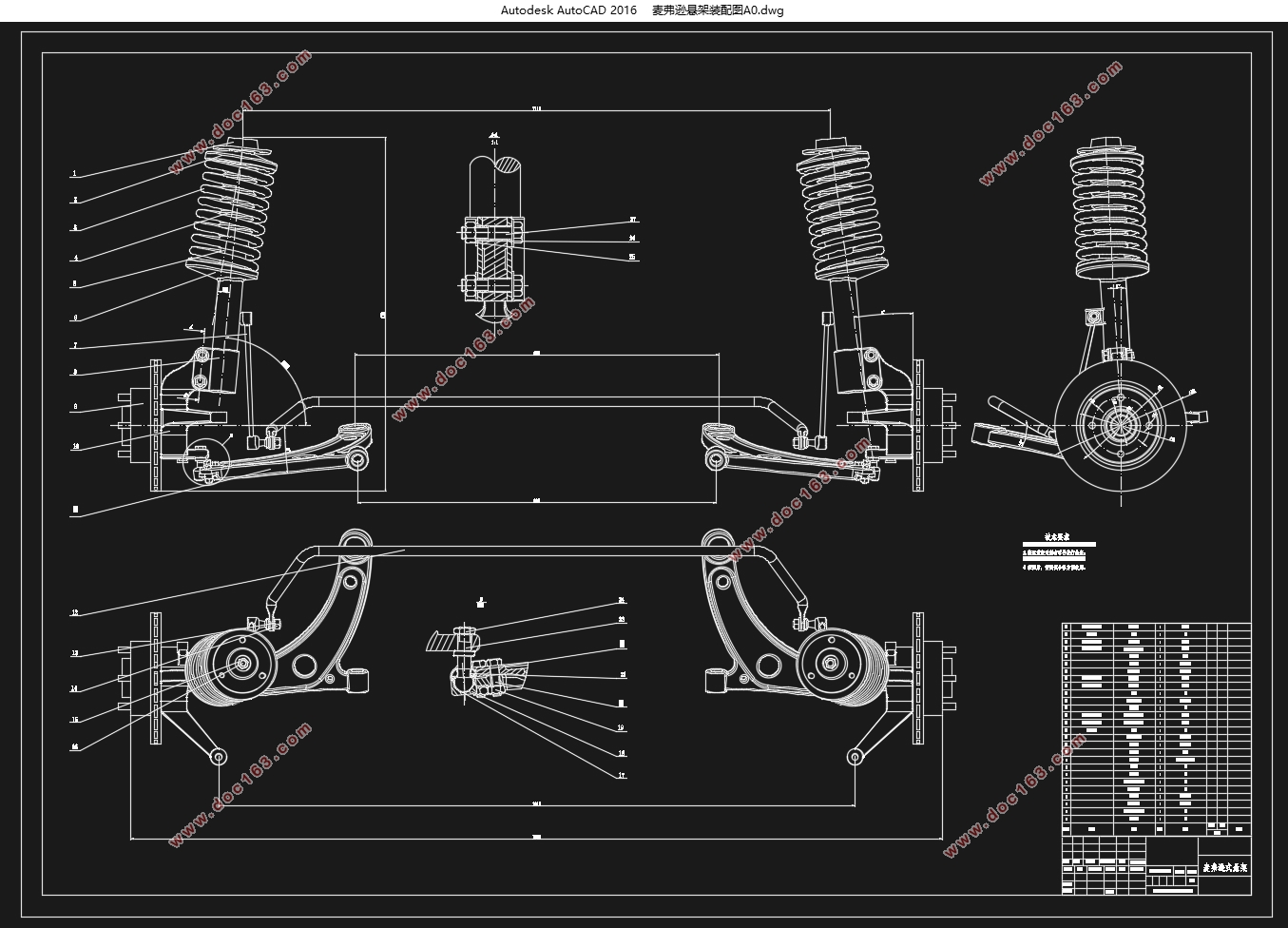
某A0级轿车前悬架系统(麦弗逊式独立悬架)设计(含CAD图,CATIA三维图)(任务书,开题报告,文献摘要,外文翻译,论文说明书14100字,CAD图5张,CATIA三维图)
摘要
本次设计的主要内容是:以某A0级轿车为原型,进行前悬架系统的结构设计并完成平顺性分析。
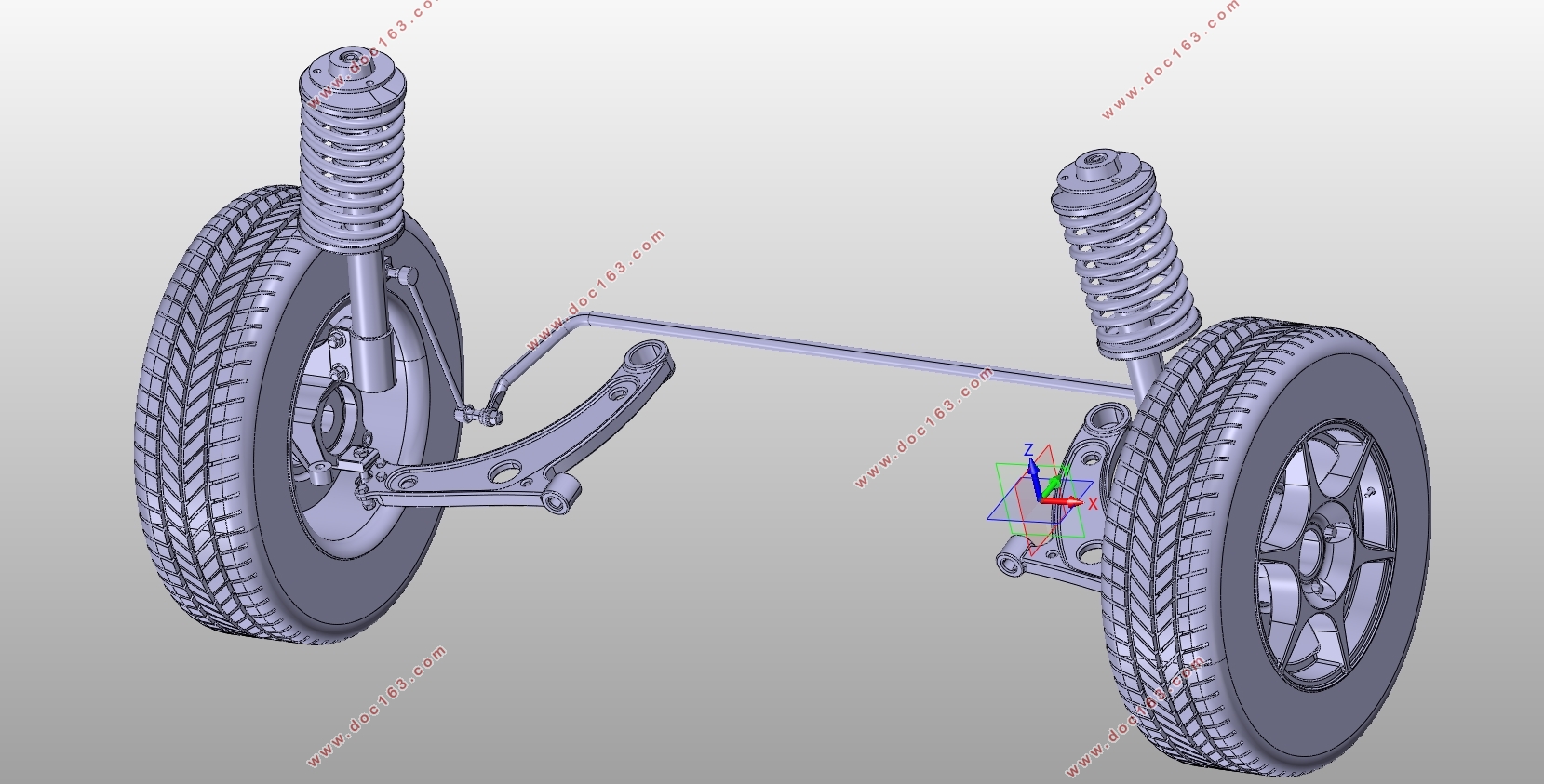
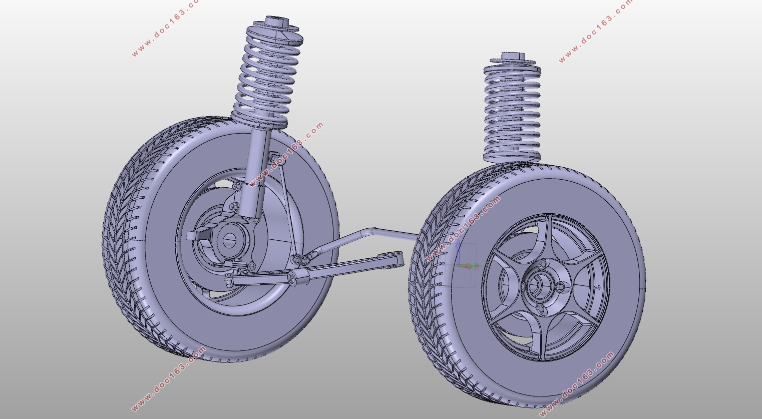
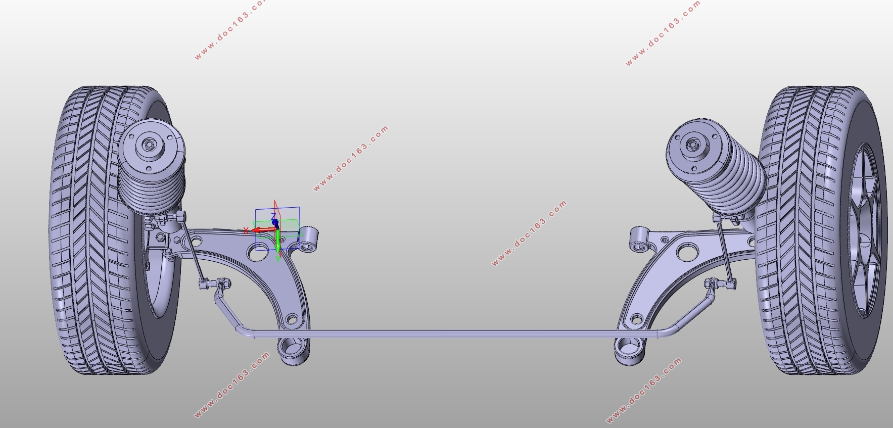
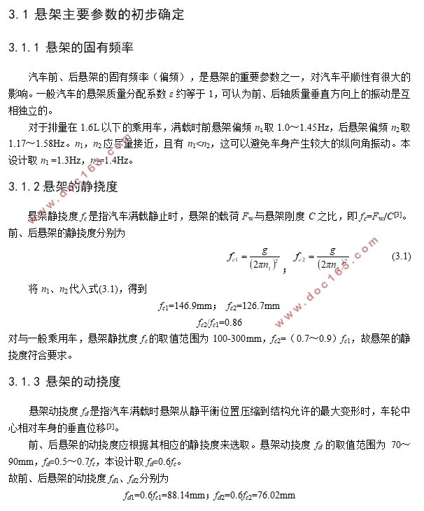
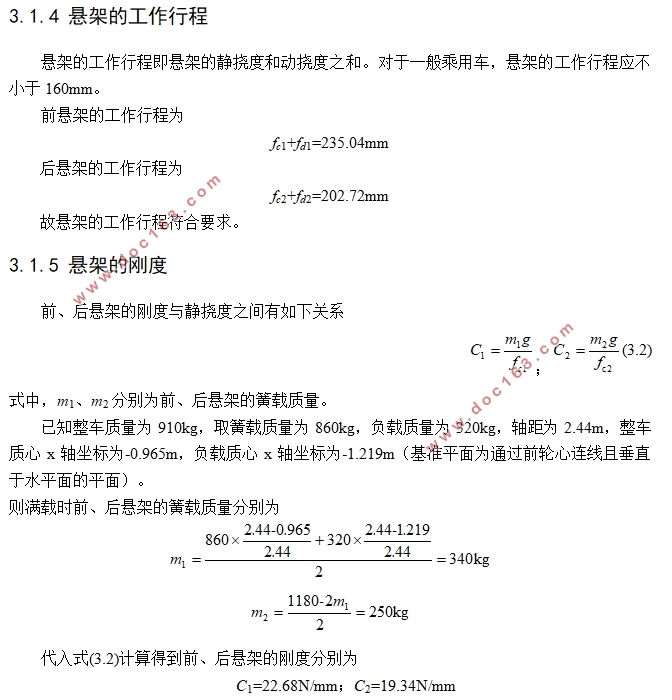
首先根据所给车型的布置形式及主要参数,对不同结构形式的前悬架进行对比分析,选择采用麦弗逊式独立悬架。悬架设计方案确定后,初步选定悬架的性能参数(包括悬架的固有频率、静挠度、刚度和簧载质量等)以及前轮定位参数。对悬架导向机构的布置参数进行设计计算,完成控制臂的设计和侧倾中心、纵倾中心的校验。根据初定的悬架的刚度进行弹性元件(螺旋弹簧)的参数设计,并检验弹簧的刚度和强度,使其满足使用需求。再根据悬架的相对阻尼系数,计算减振器的性能参数和主要尺寸,为悬架匹配合适的减振器,并且验算减振器活塞杆是否满足强度要求。然后设计横向稳定杆,使车辆具有合适的侧倾角刚度。完成零件设计后,用CATIA绘制三维图并完成装配。最后根据设计好的悬架参数,使用MATLAB/Simulink建立二自由度汽车振动模型,并进行平顺性分析。仿真得到的车身加权加速度均方根值和悬架的幅频特性曲线显示,该振动系统平顺性良好。 [资料来源:www.THINK58.com]
关键词:麦弗逊式独立悬架;减振器;三维建模;二自由度振动系统
Abstract
The main content of this design is: takeing a A0 class car as the prototype, design the structure of the front suspension system and complete theride comfort analysis.
First, according to the layout and the main parametersof the given model, different structure forms of front suspension are compared, and Mcpherson independent suspension is selected from them. After the scheme of the suspension designing is determined, the performance parameters of the suspension (including the natural frequency, static deflection, stiffness and sprung mass) and the front wheel alignment parameters are determined.The parameters of the suspension guiding mechanism are designed and calculated.The control arm is designed androll center and longitudinal center of the suspension is verified. Then according to the initialstiffness of suspension,parametersof elastic element (spiral spring)is designed, and the rigidity and the strength of the spring are tested to meet the demand of using. Next, according to the relative damping coefficient of the suspension, the performance parameters and the main size of the vibration damper are calculated in order to matchthe vibration damperwith the suspension and check whether the piston rod to meet the strength requirements.Then the horizontal stabilizer bar is designed, so that the vehicle has a suitable rolling angle stiffness.After finishing designing the parts, use CATIA to establish three-dimensional models and complete the assembly.Finally, according to the designed suspension parameters, the two degrees of freedom vehicle vibration model is established by MATLAB/Simulink, and the vehicle ride comfort is analyzed.The weighted acceleration root mean square value of the vehicle body and the amplitude frequency characteristic curve of the suspension are obtained, which show that the vibration system has good ride performance. [版权所有:http://think58.com]
Keywords:McPherson suspension;vibration damper;three-dimensional modeling;two degrees of freedom system
[资料来源:www.THINK58.com]
[资料来源:www.THINK58.com]


[资料来源:www.THINK58.com]
目录
摘要 I
Abstract II
第1章 绪论 1
1.1 悬架概述 1
1.2 悬架的发展历史和研究现状 1
1.3 设计的目的及意义 2
1.4 设计的主要内容 3
第2章 悬架结构方案的分析 4
2.1 非独立悬架和独立悬架 4
2.2 独立悬架的评价指标 4
2.3 前悬架结构方案的确定 5
第3章 悬架主要参数的确定和导向机构的设计 6
3.1 悬架主要参数的初步确定 6
3.1.1 悬架的固有频率 6
3.1.2 悬架的静挠度 6
3.1.3 悬架的动挠度 6
3.1.4 悬架的工作行程 7
3.1.5 悬架的刚度 7
3.2.5 前轮定位参数 7
3.2导向机构的设计 9
3.2.1 导向机构的受力分析 9
3.2.2 导向机构的布置参数 9
3.2.3 控制臂的设计 11
3.2.4 控制臂的三维建模 11
第4章 悬架主要零件的设计计算 12
4.1螺旋弹簧的设计 12
4.1.1 弹簧形式和材料的选择 12
4.1.2 弹簧基本参数的计算 13
4.1.3 弹簧其他参数的确定 14
4.1.4 螺旋弹簧的校核 15
4.1.5 螺旋弹簧的三维建模 16
4.2 减振器的设计 17
4.2.1 减振器的工作原理 17
4.2.2 减振器结构类型的选择 17
4.2.3 减振器主要参数的确定 17
4.2.4 活塞杆强度的校核 20
4.2.5 减振器的三维建模 20
4.3 横向稳定杆的设计 20
4.3.1 横向稳定杆的作用与原理 20
4.3.2 横向稳定杆参数的确定 21
4.3.3 横向稳定杆的三维建模 23
第5章 基于MATLAB/Simulink的汽车振动系统平顺性分析 24 [资料来源:www.THINK58.com]
5.1 汽车平顺性的概念及研究目的 24
5.2 二自由度振动系统的平顺性分析 24
5.2.1 1/4汽车振动模型的建立 24
5.2.2 二自由度振动系统的Simulink建模 26
5.2.3 用加权加速度均方根值法评价平顺性 27
5.3 二自由度振动系统的传递特性 29
第6章 结论 32
参考文献 33
致谢 34 [来源:http://think58.com]
下一篇:大型半挂油罐车结构设计与轻量化优化(含CAD零件装配图,CATIA三维图)
