
纯电动汽车电机控制器硬件电路设计(含CAD图,CATIA三维图)

1.无需注册登录,支付后按照提示操作即可获取该资料.
2.资料以网页介绍的为准,下载后不会有水印.资料仅供学习参考之用.
密 惠 保
纯电动汽车电机控制器硬件电路设计(含CAD图,CATIA三维图)(任务书,开题报告,文献摘要,外文翻译,论文说明书16000字,CAD图3张,CATIA三维图)
摘要
自从人类进入第二次工业革命时代开始,汽车这一交通工具得到迅速发展,汽车技术也不断得到发展和改进,从最初兴起的一次电池电动汽车开始,由于电池成本及电动控制技术的匮乏,后来被以燃油为动力的内燃机汽车所取代,直到上世纪50年代,电动汽车的发展开始复苏。为了缓解和解决当前世界的能源危机和日益严峻的环境污染,国际社会一致认同大力发展新型能源动力汽车是当今汽车行业的发展趋势。而纯电动汽车以其零排放、低耗能等诸多优点,借助于电动汽车研究的深入,相关电子器件和电动控制技术的成熟,终于迎来了蓬勃发展的春天。
当前纯电动汽车的研究主要聚焦于三个方面:整车控制系统、电池管理系统和电机控制系统。本论文即着力于设计一款纯电动汽车电机控制器的硬件电路,针对于应用范围广泛的三相交流异步电机进行研究,对功率模块硬件、主控板、驱动板以及各种硬件保护等电路展开分析与设计,并使用Altium Designer绘制电机控制器的各选型芯片外围控制电路和设计采集信号的调理电路等各部分硬件电路。
本论文以介绍纯电动汽车电机控制器的研究现况为切入点,了解当前的电机控制器的主流研究方向以及纯电动汽车电机控制相关理论,确立了本毕业设计的研究对象,在此基础上加深研究,完成设计需求和总体设计方案,选择MOSEFT智能功率模块作为电机控制器的功率逆变器件,设计多个MOSEFT管并联结构。接着设计电机控制器的主控板和驱动板硬件电路,以最小系统芯片TMS320F28035PN为核心设计了其外围电路,设计了电流采集电路、电源转换电路、驱动电源控制电路、转速信号采集电路、CAN通讯电路、加速和制动踏板信号采集电路、挡位及温度信号采集电路和硬件故障保护电路等;驱动板电路设计包括驱动电路设计、相电压采集电路、上下板件接插件设计等;并对纯电动汽车电机控制器的硬件外壳进行了三维建模设计和优化;最后对设计的部分硬件电路使用NI Multisim软件仿真实验,分析实验结果,得出结论并分析和改进设计的电路原理图。
[来源:http://think58.com]
关键词:纯电动汽车;电机控制器;硬件电路设计;电路仿真
ABSTRACT
Since the human race into the second industrial revolution era, the car has been rapidly developed, automotive technology has also been developed and improved .Fromthe beginning of initial rise of the battery electric car,due to battery costs and lacking of electric control technology, it was replaced by fuel-powered internal combustion engine vehicleslater.Until the 1950s, the development of electric vehicles began to recover. In order to alleviate and solve the current world energy crisis and increasingly serious environmental pollution, the international community agreed that vigorous development of new energy-powered cars is the main trend of today's auto industry. The pure electric vehicle with its zero emissions, low energy consumption and many other advantages, with the help of electric vehicle research in depth, the relevant electronic devices and electric control technology is mature, and finally get a thriving development. [资料来源:THINK58.com]
Currently,the pure electric vehicle research focused on three aspects: vehicle control system, battery management system and motor control system. This paper focuses on the design of thehardware circuit of pure electric vehicle motor controller. For the wide range of applications of three-phase AC induction motor,analyse and design its power module hardware, the main control board, driver board and a variety of hardware protection circuit, and use Altium Designer to draw the selected chip peripheral control circuit of the motor controller and design the signal acquisition circuit and other parts of the hardware circuit.In this paper, the research status of pure electric vehicle motor controller is introduced, and the current research direction of motor controller and the theory of motor control of pure electric vehicle are established,the research object of this graduation design is established. The MOSEFT intelligent power module is selected as the power inverter device of the motor controller, and the MOSEFT tube parallel structure is designed to complete the design and meet the design requirements. Then, the hardware circuit of the main control board of the motor controller is designed, and the peripheral circuit is designed with the minimum system chip TMS320F28035PN and its external circuit is designed,.The current acquisition circuit, the power conversion circuit, the driving power control circuit, the speed signal acquisition circuit, the CAN communication circuit, the brakeand acceleration pedal signal acquisition circuit, the gear and temperature signal acquisition circuit and the hardware protection circuit is included. The design of the drive board circuit includes the design of the driving circuit, the phase voltage acquisition circuit, the upper and lower board connector design. The hardware shell structure of the motor controller is designed and optimized in three dimensions. Finally, some of the hardware circuits are designed using NI Multisim software Simulation experiments, analyse the experimental results, draw conclusions, analyse and improve the design of the circuit schematic.
KeyWords:EV;motor controller;hardware circuit design; circuit simulation
论文主要研究内容分析
本毕业设计论文主要任务是设计一款纯电动汽车电机控制器硬件电路,涉及纯电动汽车驱动电机控制系统各个方面的功能需求,控制系统的对象是交流异步电机,应用于纯电动低速汽车,论文结构大体上如下:
第一章先阐释研究课题的大方向,对国内外的在这个领域的研究现状进行了解介绍,引出纯电动汽车电机控制器硬件电路的设计思路。
第二章对纯电动汽车电机控制相关理论进行介绍,介绍了电机控制器的结构、工作原理、技术要求及控制理论策略分析;纯电动汽车电机控制器功率模块的设计,功率模块是控制器的核心功能模块,只有确定功率模块的设计方案才能进行下一步的设计。这部分包括总体方案设计、功率模块电路设计、驱动电路及保护措施。
第三章设计硬件电路主控板电路,先定下总体设计方案,之后主要设计的内容有最小系统电路,电源转换电路,CAN通讯电路,电流采集电路,电源控制电路,转速信号电路,温度采集电路,档位控制电路,以及硬件电路保护电路。
第四章对驱动板电路进行设计,驱动电路、相电压采集电路、上下板间接插件设计等。最后对控制器的外壳用三维设计软件进行了建模。以上主要就是本论文的设计部分的工作。 [资料来源:http://www.THINK58.com]
第五章是对设计内容的实验研究,针对设计的硬件电路的可行性,利用电路仿真软件NI Multisim对硬件电路进行仿真实验,设定输入的信号类型,观察输出信号,分析是否存在可行性。并对设计的方案进一步的分析思考和改进。
第六章总结了毕业设计中纯电动汽车电机控制器设计工作,找出设计过程中的不足之处进行说明,对可能进一步的设计改进和研究工作的实施内容进行分析,展望后续的研究工作。
本论文对于研究交流异步电机控制器的硬件设计及仿真调试具有一定的参考意义。
[资料来源:http://think58.com]
目录
摘要 I
ABSTRACT II
第1章绪论 1
1.1 研究背景与意义 1
1.2 国内外研究现状 2
1.3 论文主要研究内容分析 3
第2章硬件电路需求定义及总体设计 5
2.1 电机控制系统需求定义 5
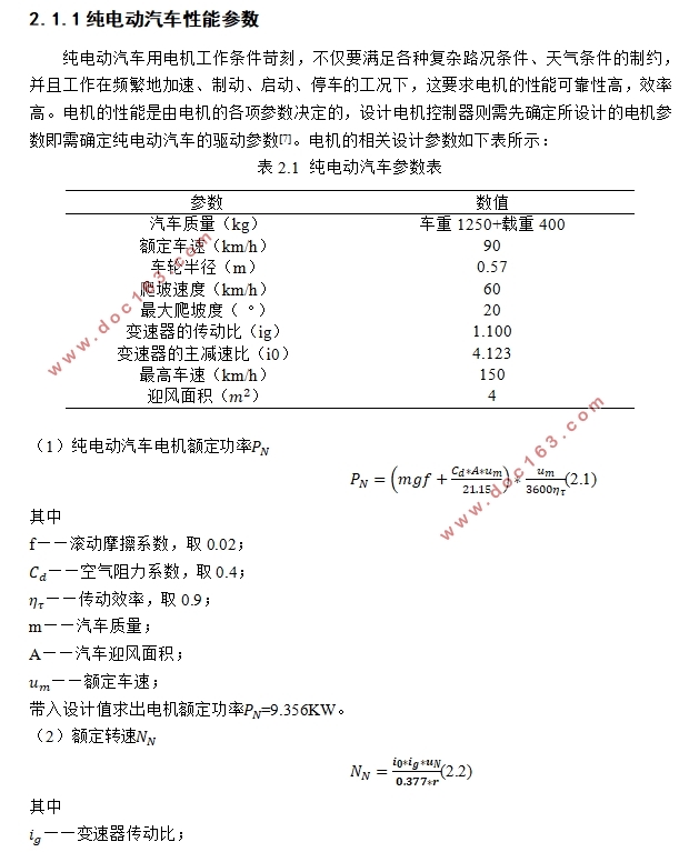
2.1.1纯电动汽车性能参数 5
2.1.2电机控制器基本参数 6
2.1.3 电机控制系统的基本要求 7
2.1.4主流电机控制策略的分类 7
2.2电机控制系统的总体设计 8
2.3 电机控制器功率器件选择设计 9
第3章电机控制器主控板硬件电路设计 11
3.1 MCU最小系统电路设计 11
3.1.1 最小系统芯片TMS320F28035PN 11
3.1.2 TMS320F28035PN最小系统电路 11
3.1.3 最小系统时钟振荡电路设计 12
3.1.4 JTAG接口电路 13
3.1.5 复位电路 14
[来源:http://think58.com]
3.2 电流信号调理电路设计 14
3.3 电机转速信号调理电路设计 15
3.4 驱动电源转换电路设计 16
3.5 电源控制电路设计 17
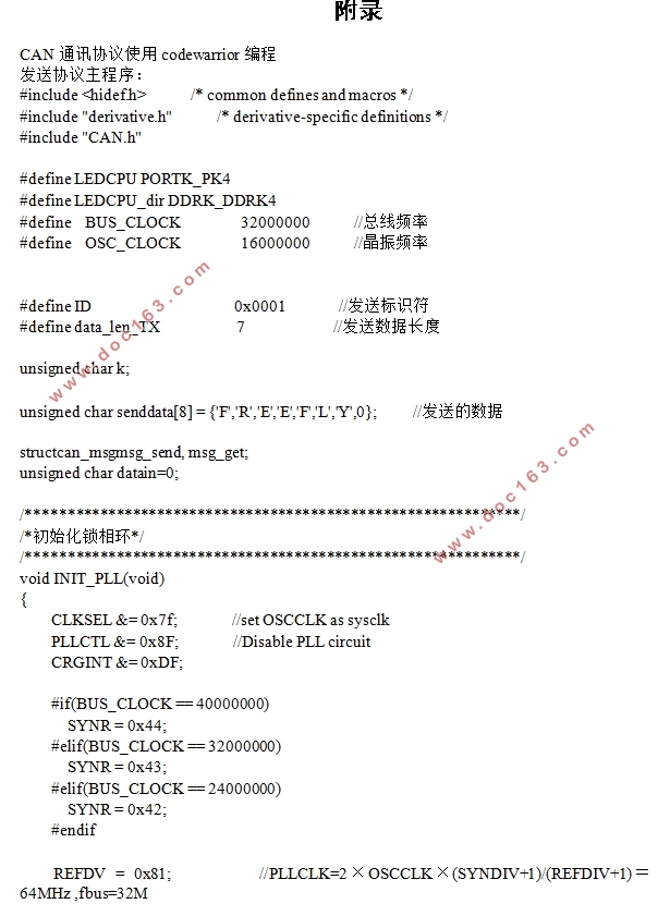
3.6 CAN通讯电路设计 18
3.7 制动踏板及加速踏板信号电路设计 19
3.8 档位、温度信号电路设计 20
第4章电机控制器驱动板硬件电路设计 21
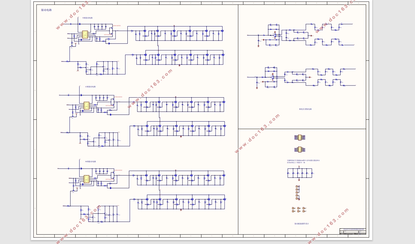
4.1 驱动电路设计 21
4.2 相电压采集电路设计 22
4.3上下板间接插件电路设计 23
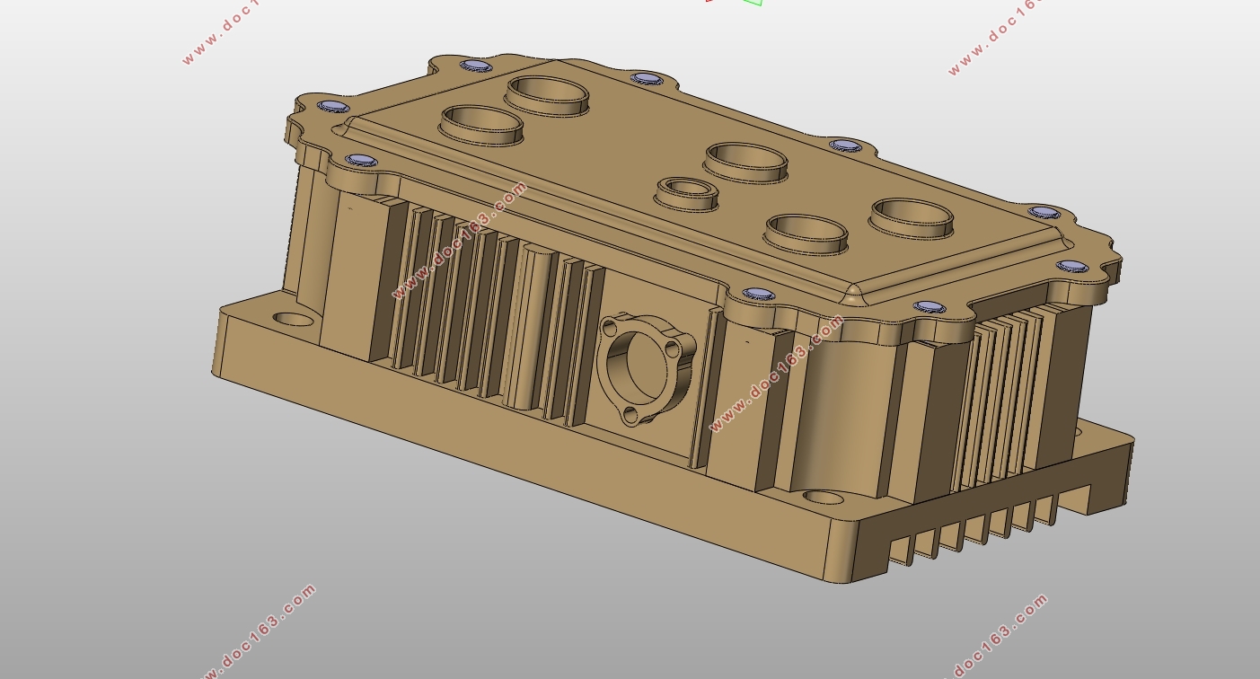
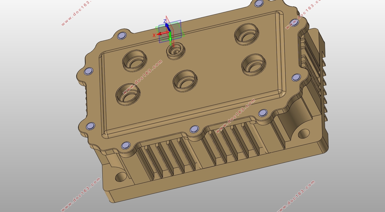
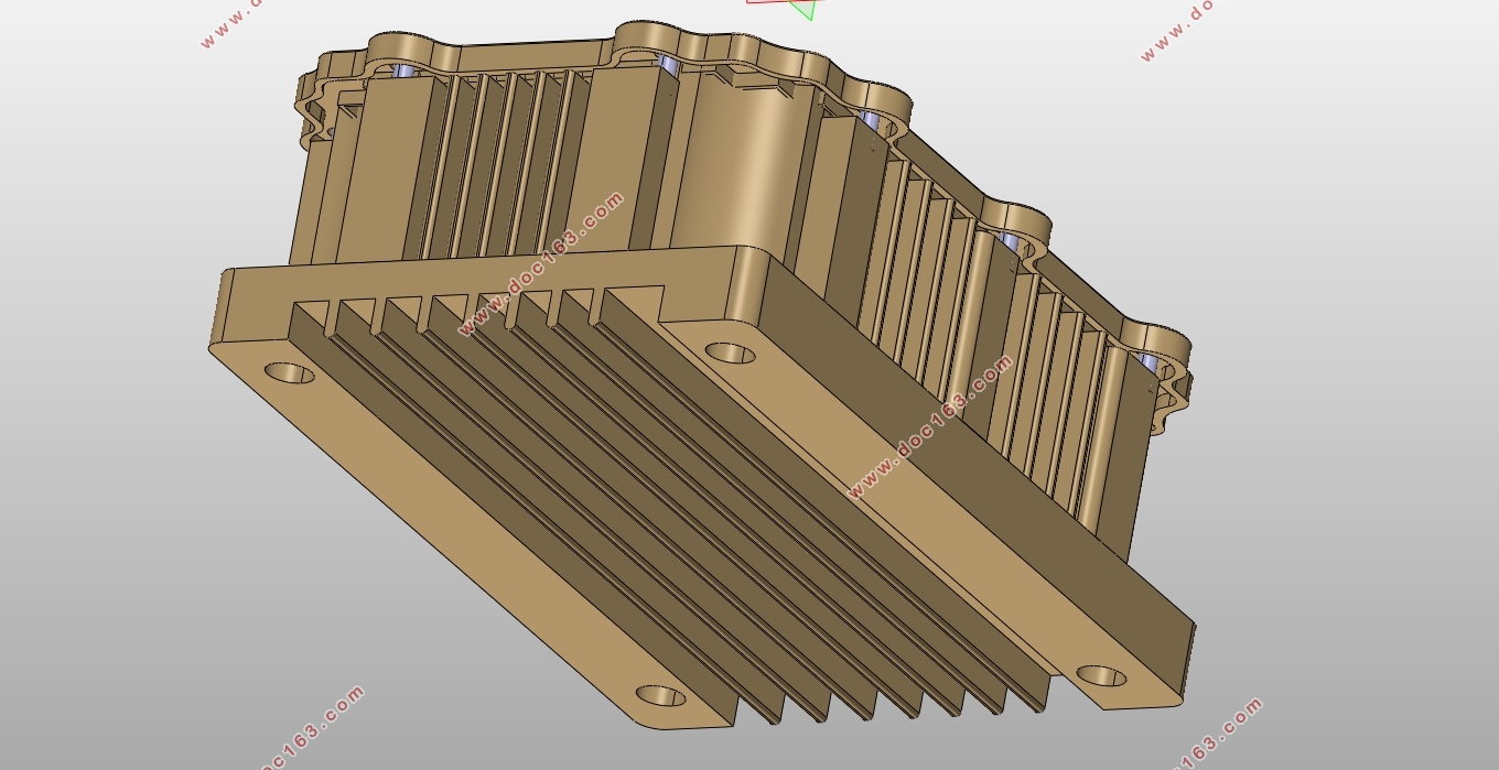
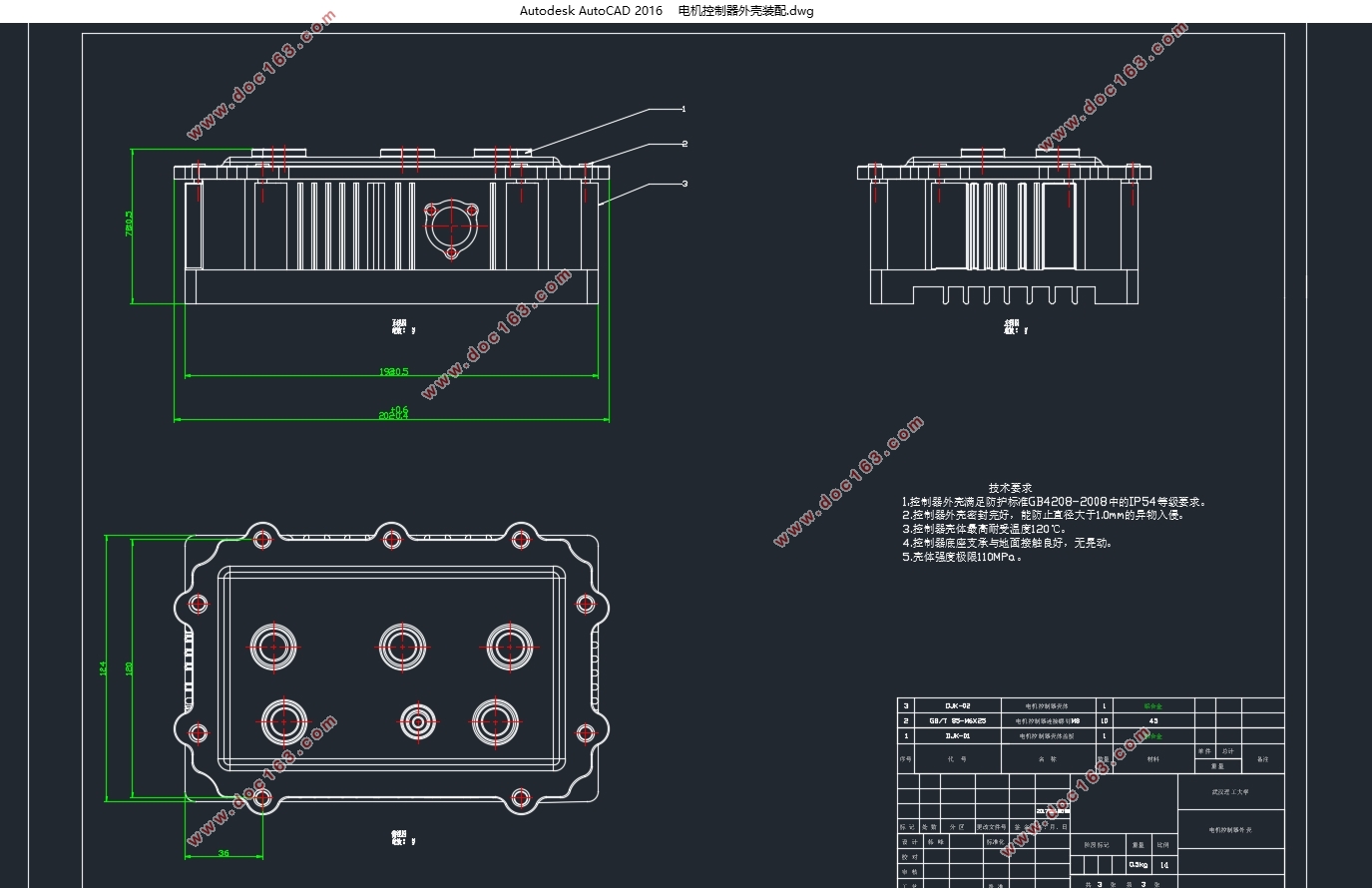
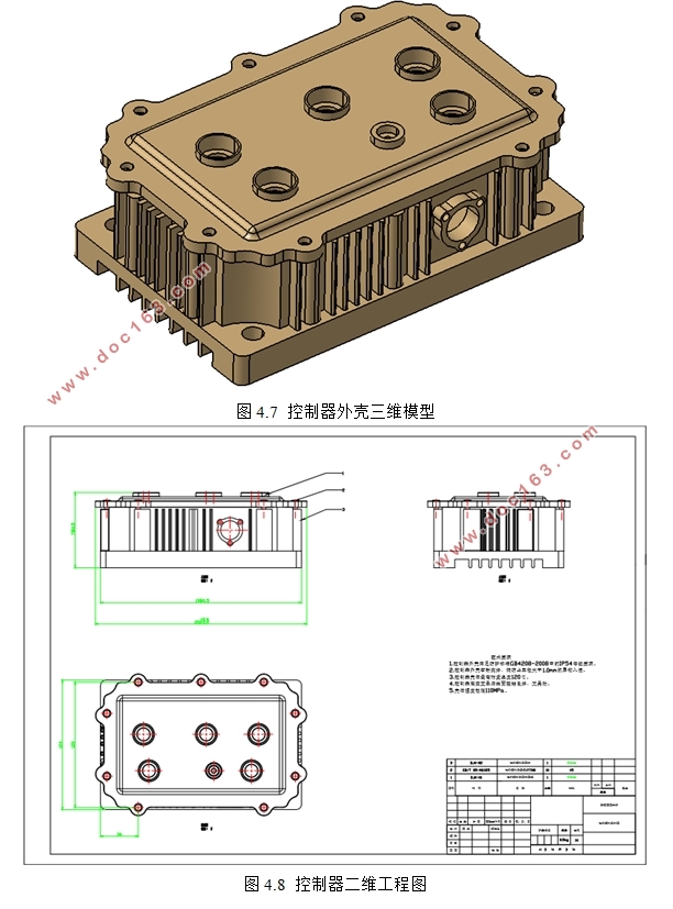
4.5 控制器外壳结构设计 24
4.5.1结构设计要求和注意事项 24
4.5.2 电机控制器外壳的CATIA建模和工程图 24
第5章控制器硬件电路仿真实验 26
5.1 硬件电路仿真综述 26
5.2 基于Multisim的电流采集电路仿真 26
5.3 基于Multisim的电机转速信号调理电路仿真 29
[资料来源:THINK58.com]
第6章总结与展望 31
致谢 32
参考文献 33
附录 34
上一篇:汽车盘式制动器参数化建模及分析(含CAD零件图装配图)