基于ADAMS的重型车悬架系统仿真分析与优化(含CAD图,CATIA三维图)
1.无需注册登录,支付后按照提示操作即可获取该资料.
2.资料以网页介绍的为准,下载后不会有水印.资料仅供学习参考之用.
密 惠 保
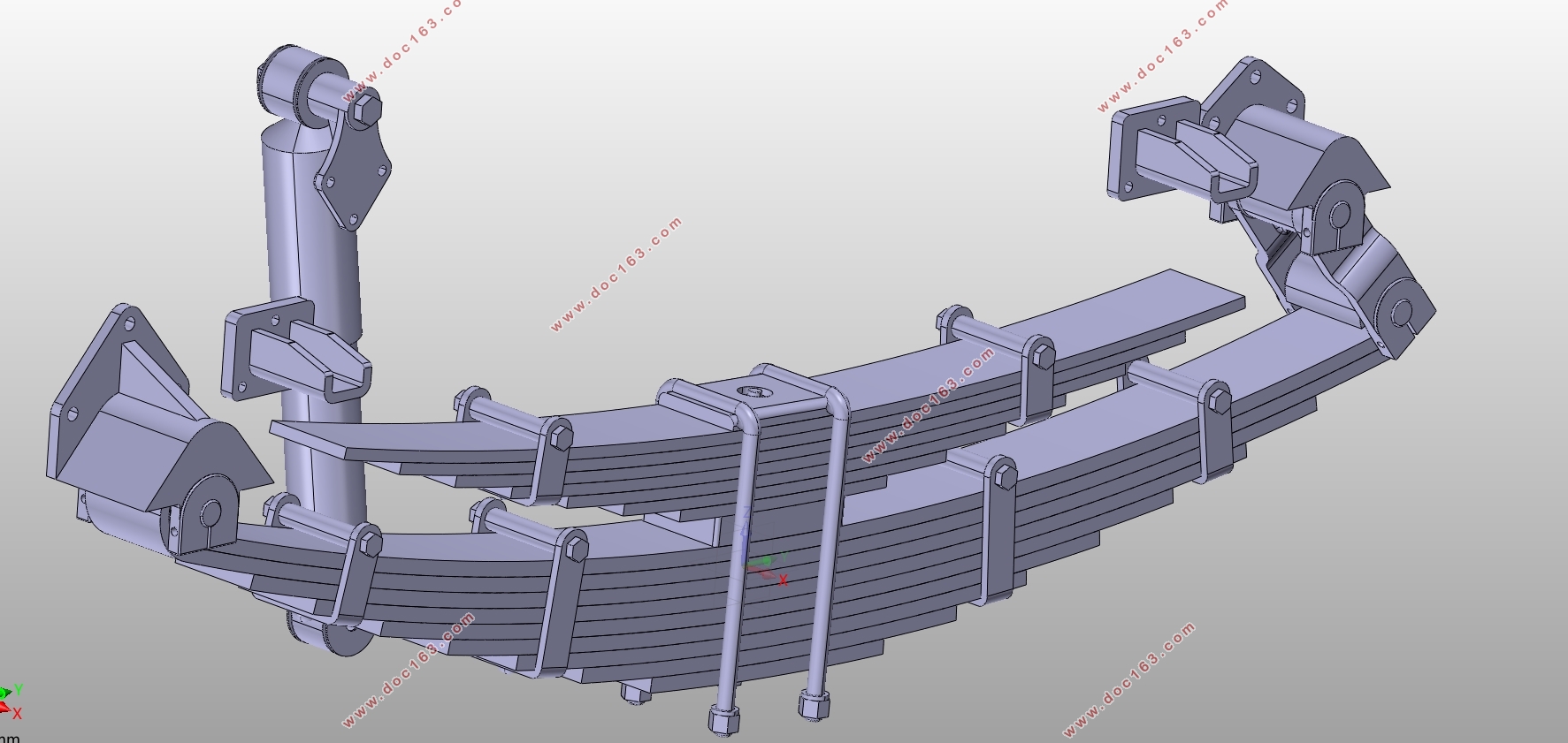
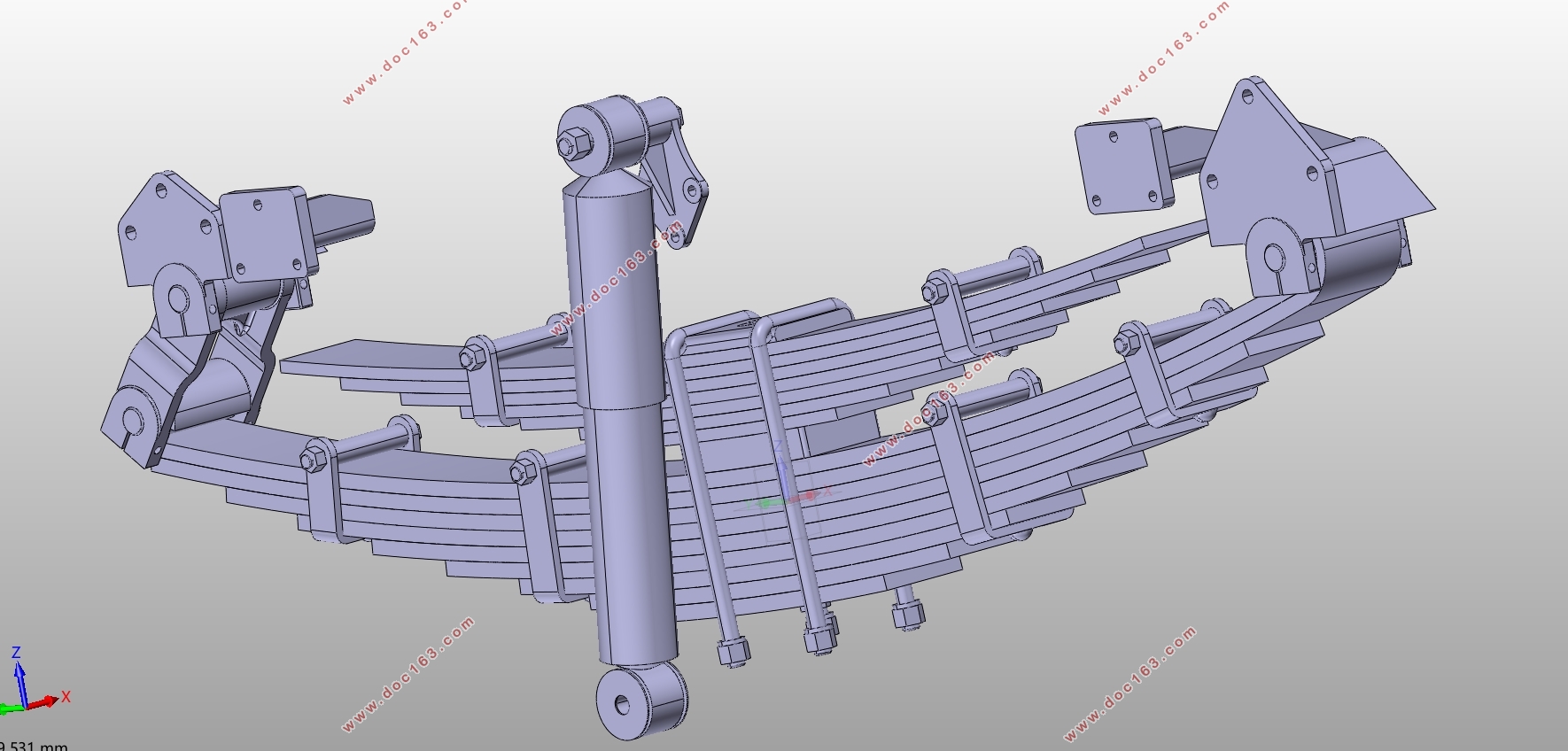
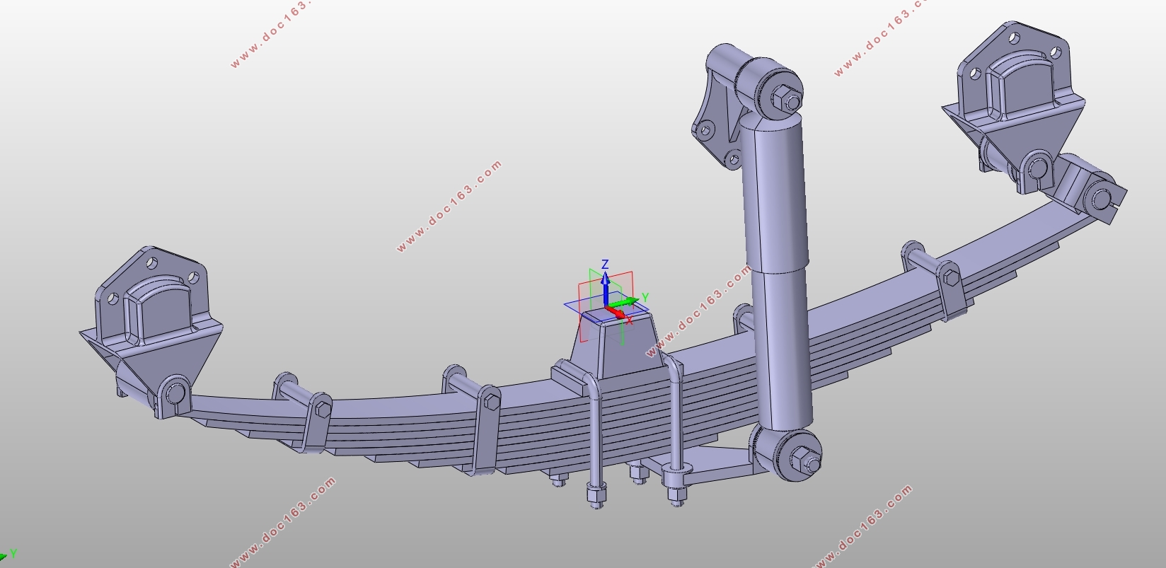
基于ADAMS的重型车悬架系统仿真分析与优化(含CAD图,CATIA三维图)(任务书,开题报告,文献摘要,外文翻译,论文说明书14000字,CAD图6张,CATIA三维图)
摘要
悬架系统属于汽车行驶系统,是汽车上的重要部件之一。作为车轮与车身的连接部件,它承担着两者之间的力和力矩。除此之外,由于弹性元件和减振器的存在,它还可以消耗车轮与车身相对运动产生的冲击能量,衰减振动。汽车行驶平顺性和操纵稳定性均与悬架系统密切相关。由此可见,悬架系统的设计在汽车设计中十分重要。
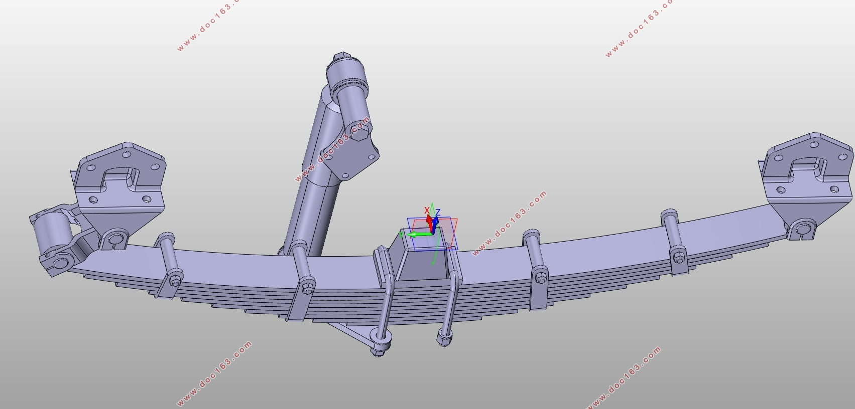
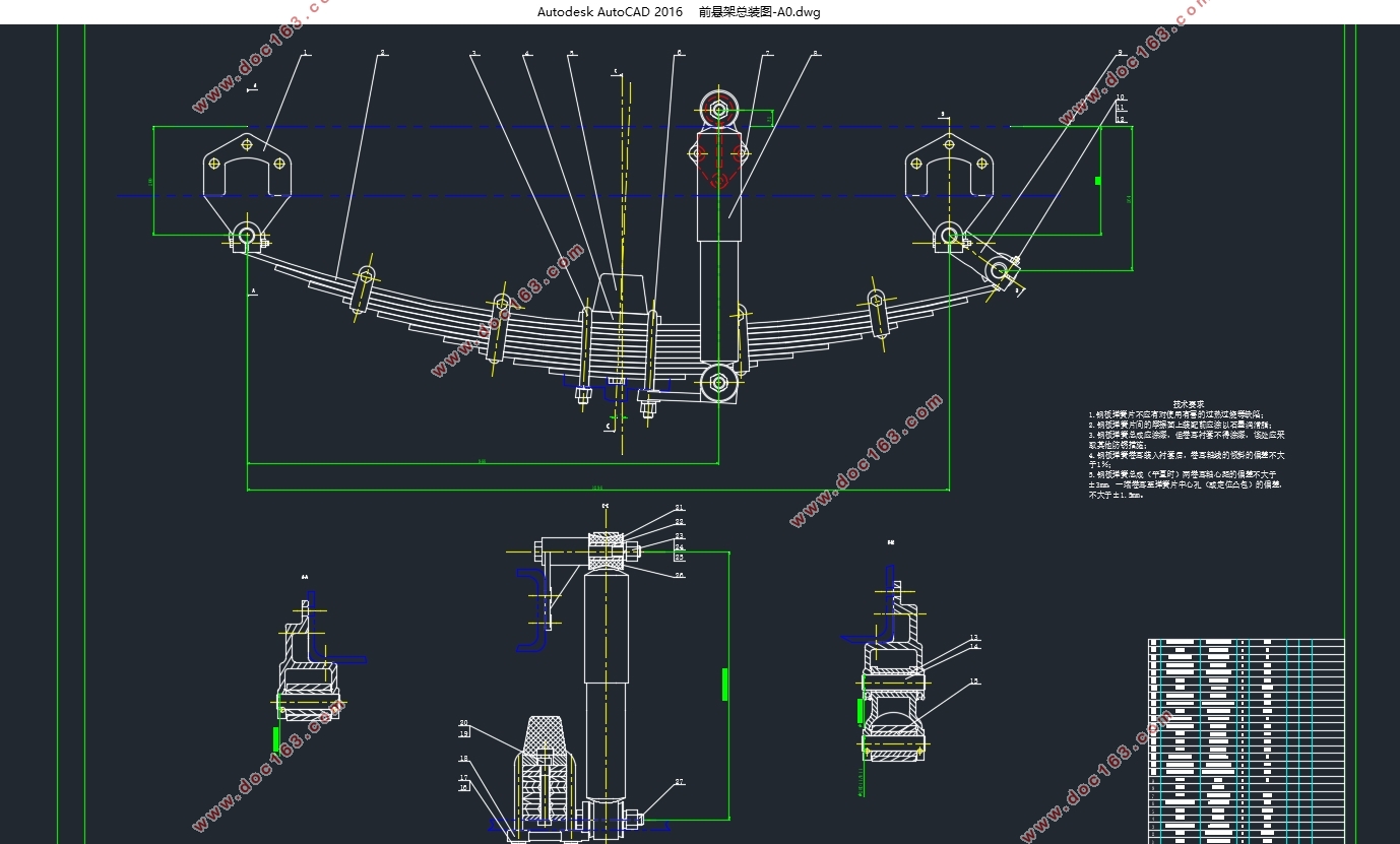
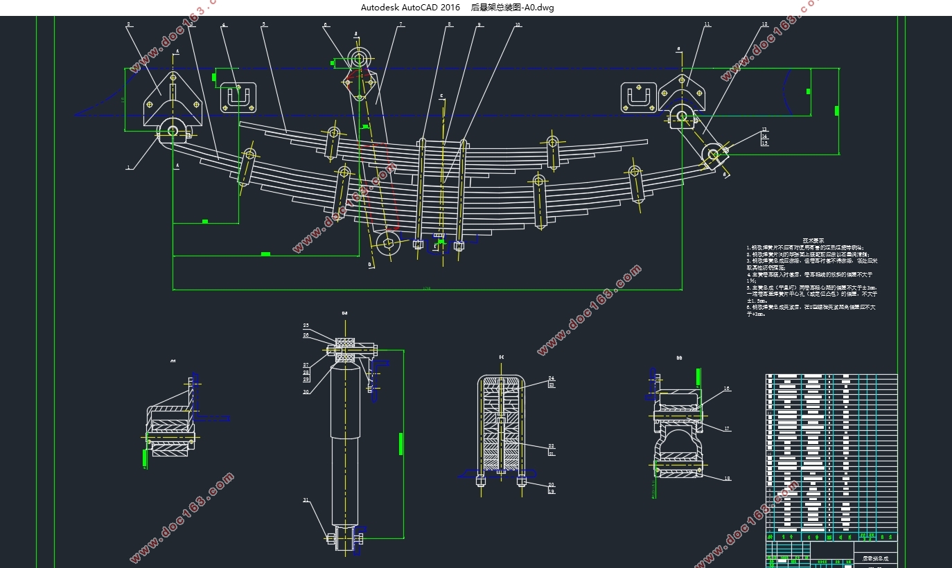
本文主要研究重型货车悬架系统的选型与设计。首先熟悉悬架系统相关知识,进行结构选型,然后运用汽车设计相关理论知识分别对钢板弹簧和减振器的主要尺寸进行设计计算,再借助三维建模软件CATIA和二维绘图软件AutoCAD对悬架系统及其零部件进行绘制,最后运用仿真分析软件ADAMS建立振动仿真模型,并研讨悬架系统刚度和阻尼与汽车行驶平顺性之间的关系。
关键词:悬架系统;钢板弹簧;减振器;刚度;阻尼系数
Abstract
Suspension system is one of the important parts of the car. It connectsthe wheels and the body, and transmits force and torque. In addition, it can also ease the impact of road surface to the body and attenuate vibration. A good suspension system ensures that the car has good ride comfort and handling stability. Therefore, the suspension system design in the automotive design is essential.
This paper mainly studies the design of heavy truck suspension system. First of all, I was familiar with the knowledge about the suspension system andselected the structure. Then,I used the theoretical knowledge of automotive design to calculatethe main dimensions of leaf springs and shock absorberrespectively.Next, I resorted to the 3D modeling software CATIA and 2D drawing software AutoCAD to draw the suspension system and itscomponents. Finally,I used the virtual prototyping software ADAMS to establish the vibration simulation model and analyzed the influence of the stiffness and damping of the suspension system on the ride comfort of the vehicle.
Key words: suspension system; leaf spring; shock absorber; stiffness; damping coefficient
3.1已知设计参数
本次设计是以中国重汽集团开发的豪沃牌ZZ1167K501GE1载货汽车为例,设计悬架系统所需的基本参数如下:
轴距:4700mm;
整车整备质量:5810kg;
满载质量:16000kg;
满载时,前轴负荷G1:52267N;后轴负荷G2:104533N;
空载时,前轴负荷G01:29645N;后轴负荷G02:28469N;
前轴簧下部分荷重Gu1:7840N;后轴簧下部分荷重Gu2:12544N;
前轮距:1960mm;后轮距:1860mm;
轮胎规格:275/80R22.5。
根据上述参数计算满载时前、后轴一侧钢板弹簧的载荷:
F_w1=((G_1-G_u1 ))⁄(2=((52267-7840))⁄(2=)) 22213.5N(3.1)
F_w2=((G_2-G_u2 ))⁄(2=((104533-12544))⁄(2=)) 45994.5N(3.2)
空载时后轴一侧钢板弹簧的载荷:
F_02=((G_02-G_u2 ))⁄(2=((28469-12544))⁄(2=)) 7962.5N(3.3)
[版权所有:http://think58.com]


目录
第1章绪论 1
1.1课题研究意义 1
1.2国内外研究现状 1
1.3课题研究内容 2
第2章悬架系统结构型式与设计要求 3
2.1悬架系统的功用和组成 3 [资料来源:http://think58.com]
2.2悬架系统的结构形式 3
2.3悬架系统的设计要求 4
第3章悬架系统主要参数的确定 5
3.1已知设计参数 5
3.2悬架静挠度fc的选择 5
3.3悬架动挠度fd的选择 6
3.4后悬架主、副簧刚度的分配 6
第4章悬架系统主要零部件的设计计算 8
4.1钢板弹簧的设计计算 8
4.1.1满载弧高fa的选择 8
4.1.2钢板弹簧长度L的选择 8
4.1.3钢板弹簧片数及断面尺寸的确定 8
4.1.4钢板弹簧各片长度Li的确定 11
4.1.5自由状态下钢板弹簧总成弧高及各片曲率半径的计算 13
4.1.6钢板弹簧总成弧高的验算 17
4.1.7钢板弹簧强度的验算 18
4.2减振器的设计计算 19
4.2.1相对阻尼系数ψ的选择 20
4.2.2减振器阻尼系数δ的计算 20
[来源:http://www.think58.com]
4.2.3最大卸荷力F0的计算 21
4.2.4工作缸直径D的确定 21
4.3三维模型的建立 22
第5章悬架系统的仿真分析 23
5.1仿真模型的建立 23
5.2仿真与结果分析 24
第6章结论 26
参考文献 27
致谢 28 [资料来源:www.THINK58.com]
下一篇:汽车盘式制动器参数化建模及分析(含CAD零件图装配图)
