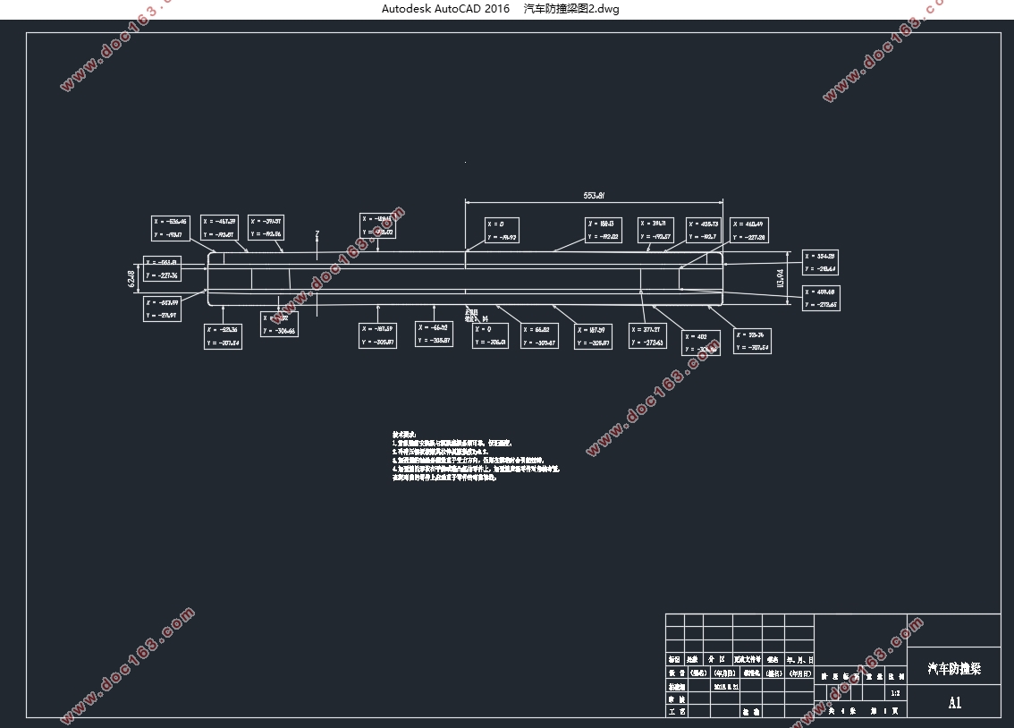
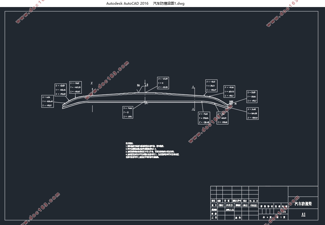
汽车防撞梁结构设计及性能分析(含CAD图)

1.无需注册登录,支付后按照提示操作即可获取该资料.
2.资料以网页介绍的为准,下载后不会有水印.资料仅供学习参考之用.
密 惠 保
汽车防撞梁结构设计及性能分析(含CAD图)(任务书,开题报告,文献摘要,外文翻译,论文说明书23000字,CAD图3张)
摘 要
随着科技的进步和经济的发展,我国的汽车工业愈来愈强大,汽车保有量也有所增加,因此汽车在各种环境下发生碰撞事故的几率也大大提升,不少人也因此丧命。发生概率最大的交通事故是侧面碰撞,同时它也是死亡率最高的事件之一。汽车的侧面是车门,强度较为薄弱。不一样的防撞梁结构导致不一样的强度,所以挑选不一样的结构能提升汽车碰撞的低危险性,减少车员伤亡,我打算对汽车防撞梁进行优化设计。
本论文研究的同一种材料的不同结构对防撞梁所造成影响。改变某一防撞梁结构的铺陈形式或材料,得出重量与性能的对比。使用工字梁,口字梁或凹字梁结构以ug/catia、ansys设计并分析出最佳的铺陈设计,使防撞梁的性能得到最好的发挥。
随着经济和科技的发展,越来越多的汽车厂商和研究机构也认可了计算机模拟验证方法,由研究的目的而采用ug/catia修改防撞梁模型,删除模型的附加部件,然后将ug/catia所产生的模型导入ansys,使用ansys划分网格,形成有限元模型,模拟碰撞产生自变量然后利用这一有限元分析软件,对防撞梁结构的强度和汽车碰撞来分析和计算,得出计算结果与实验数据进行对比,验证仿真模拟实验的合理性,为汽车碰撞过程模拟分析方法提供技术参考。 [资料来源:http://think58.com]
综合模拟计算结果,碰撞过程对整车危害最大的是口子梁,其次是凹字梁,最小的是工字梁。
通过对碰撞的模拟分析,我在本论文中写了关于碰撞冲击力对防撞梁结构做强度检验的方法,而且对本论文建立的几何模型做了强度分析,得到应变和应力结果,大于了此材料的屈服极限,所以有可能断裂。再对一开始的防撞梁进行了三种形式的优化,将它转化为了工字梁,口字梁和凹字梁,并且又一次强度校核了优化结果。然后,防撞梁收到的应力返回到材料的屈服极限内,因此证明了我思路的可执行性。
本论文经典的对怎么利用有限元分析防撞梁受到精力时候的应力分布进行了介绍。我在遵守对防撞梁实行有限元分析的办法的基础上,创建了一个较为丰满的有限元分析进程。第一是要创建好防撞梁的模型,其次划分网格,再对梁结构实行约束和加载,结尾计算和分析得出结果,得到位移综合偏差和应力分析图像进行参照。通过本论文,我们低层面的了解了有限元分析方法在现代科技设计中的意义,运用方法,感觉又学到了一点新知识,虽是皮毛,却也感觉很深,令人心旷神怡,开心不已。
关键词:ANSYS,梁结构,有限元,静力分析
ABSTRACT
With the advancement of technology and economic development, China's auto industry increasingly powerful, car ownership has also increased, therefore the probability of occurrence of car crashes in a variety of environments is also greatly improved, many people have died. The maximum probability of occurrence of accidents is a side collision, it is also one of the highest mortality event. Side of the car door is, the intensity is weak. Not the same bumper beam structure results in different strength, so pick a different structure can improve the car crash low risk, reduce casualties, I'm going to the car crash beam to optimize the design.
[资料来源:http://THINK58.com]
Different structures of the same material of the present thesis on the impact of the collision caused the beam. A change in the form of elaborate bumper beam structure or materials derived contrast weight and performance. Use joist, beam or concave mouth-beam structure ug / catia, ansys design and analysis of the best lay out design, the performance of the bumper beam best play.
With the development of economy and technology, more and more car manufacturers and research institutions have recognized the computer simulation method validation by the purpose of the study and the use of ug / catia modify bumper beam model, additional components deletion model, and then ug / import ansys catia model generated using ansys mesh to form a finite element model to simulate the collision argument then use this finite element analysis software, structural strength of the bumper beam and crash cars to analyze and calculate the yield the calculation results with the experimental data were compared to verify the reasonableness of simulation experiments, provide technical reference for automotive collision simulation analysis. [资料来源:THINK58.com]
Comprehensive simulation results, the collision of the vehicle is the most damaging hole in the beam, followed by the concave-beam, I-beam is minimal.
Through simulation of the collision, I wrote in this paper about the collision impact force to the bumper beam structure for strength testing method, and geometric model of the present paper established to do strength analysis, the strain and stress results, more than this yield limit of the material, it is possible to break. And then the beginning of the impact beams were three forms of optimization, it would be conversion to beams, beams and recessed port beam, and once again the strength checking optimization results. Then, the stress impact beams received back into the material yield limit, thereby demonstrating my idea of enforceability.
The classic paper on how the use of finite element analysis of stress distribution by the bumper beam energy when introduced. I observe the implementation of the finite element analysis of crash beam approach based on creating a more plump finite element analysis process. The first is to create a model of good crash beams, followed by mesh, then the implementation of the constraints and load beam structure, the end of the calculation and analysis of the outcome of the comprehensive deviation obtained displacement and stress analysis of reference images. Through this paper, we have a low level of understanding of the finite element analysis methods in the design of modern technology, the use of the method, but also learned a little sense of new knowledge, though it is fur, but also feel a deep, refreshing, happy for them.
Keywords: ansys, beam structure, finite element, static analysis.


目 录
第1章 绪 论 1
1.1 防撞梁的介绍 1
1.2 研究背景 2
1.3 汽车碰撞国内外研究现状 3
1.3.1 国外研究现状 3
1.3.2 国内研究现状 3
1.4 国内外防撞梁结构强度研究概况 4 [来源:http://www.think58.com]
1.5 汽车侧面碰撞的研究方法 5
1.6 目前的汽车防撞梁研究现状 6
1.6.1 目前防撞梁的研究 7
1.7 课题主要研究内容 8
第2章 防撞梁撞击变形基本理论分析 10
2.1弹塑性变形理论 10
2.1.1 金属材料拉伸时的力学性能 10
2.1.2 弹塑性模型的简化 11
2.1.3 材料的强化模型 12
2.2 用于碰撞过程的基本定理 13
2.2.1 冲量定理 14
2.2.2 冲量矩定理 14
2.3 汽车防撞梁变形过程中的能量分析 14
2.3.1 能量的转化 15
2.3.2 汽车吸能装置的基本要求 16
2.4 薄壁构件变形理论 16
2.5 小结 17
第3章 碰撞研究的非线性有限元法 18
3.1引言 18
3.2 非线性有限元法基本理论 18 [资料来源:www.THINK58.com]
3.2.1线性有限元的回顾 18
3.2.2 有限元方法的三个基本步骤 19
3.2.3 等参单元 19
3.3 非线性有限元法基本理论 20
3.4 有限元数值模拟理论 20
3.5 有限元算法 20
3.5.1 拉格朗日法(LAGRANGE) 21
3.5.2 欧拉法(EULER) 21
3.5.3任意欧拉-拉格朗日法(ALE) 21
3.6 拉格朗日有限元算法介绍 21
3.7单元选择 22
3.8 接触问题 23
3.8.1 接触类型 23
3.8.2 接触算法 24
3.9 本次计算的相关软件介绍 25
3.10 小结 26
第4章 ANSYS/LS.DYNA功能和理论简介 27
4.1 ANSYS/LS.DYNA概况 27
4.2 ANSYS/LS.DYNA程序功 27
4.2.1单元和材料类型 27
4.2.2 接触分析模块 28
4.2.3 沙漏理论及简化积分 29
4.2.4 LS-DYNA前后处理 29
第5章 防撞梁结构性能分析 31
5.3参数设定 35
5.4网格划分 36
展望致谢 45
参考文献 46 [版权所有:http://think58.com]
下一篇:侧翻稳定性试验车设计(含CAD零件装配图,CATIA三维图)
